
User's Manual

9
4 ADDITION INFORMATION
4.1 I
2
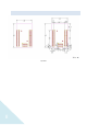
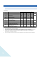
C INTERFACE
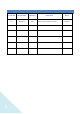
Characteristics
Symbol Parameter
Standard mode
(1)
Fast mode
(1)(2)
Unit
Min Max Min Max
t
w(SCLL)
SCL clock low time 4.7 - 1.3 -
µs
t
w(SCLH)
SCL clock high time 4.0 - 0.6 -
t
su(SDA)
SDA setup time 250 - 100 -
ns
t
h(SDA)
SDA data hold time 0 3450
(3)
0 900
(4)
t
r(SDA)
t
r(SDL)
SDA and SCL rise time - 1000 - 300
t
f(SDA)
t
f(SDL)
SDA and SCL fall time - 300 - 300
t
h(STA)
Start condition hold time 4.0 - 0.6 -
µs
t
su(STA)
Repeated Start condition setup time 4.7 - 0.6 -
t
su(STO)
Stop condition setup time 4.0 - 0.6 -
µs
t
w(STO:STA)
Stop to Start condition time (bus free) 4.7 - 1.3 -
µs
t
SP
Pulse width of the spikes that are
suppressed by the analog filter for
standard fast mode
0 50
(5)
0 50
(5)
µs
C
b
Capacitive load for each bus line - 400 - 400 pF
1. Guaranteed by design, not tested in production.
2. f
PCLK1
must be at least 2MHz to achieve standard mode I
2
C frequencies. It must be at least 4MHz to achieve fast
mode I
2
C frequencies, and a multiple of 10MHz to reach the 400kHz maximum I
2
C fast mode clock.
3. The device must internally provide a hold time of at least 300ns for the SDA signal in order to bridge the
undefined region of the falling edge of SCL
4. The maximum data hold time has only to be met if the interface does not stretch the low period of SCL signal.