
Owner`s manual


Page 9
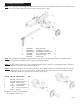
STEP 5: Connect the end of the 1/2” ID x 44” hydraulic pressure hose (1) coming from the fitting on the pump to the
fitting on the valve . See illustrations below.
STEP 6: Slide one hose clamp on the end of the 3/4” x 44” hydraulic return hose (3) that comes from the fitting on the
filter. Then connect the hose to the fitting on the valve. See illustrations below.
Area of
Detail
ITEM NO. PART NO. DESCRIPTION QTY.
1 39024600 1/2” x 44”Pressure Hose 1
2 39031600 Worm Gear Clamp 3
3 39025200 3/4” x 44” Return Hose 1
4 390406SC Auto-Return Valve 1
O/L- Obtain locally. Common fasteners available through
hardware and farm stores.
View from Top
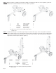
TANK/ENGINE ASSEMBLY BREAKDOWN
1 O/L 5/16”-18 UNC Nylock Nut 7
2 O/L 5/16” x 2-1/2” GR 5 Hex Bolt 1
3 O/L 5/16” x 1 GR5 Hex Bolt 4
4 O/L 5/16” x 1-1/2” GR5 Hex Bolt 2
5 39024600 1/2” x 44” Hydraulic Pressure Hose 1
6 39025200 44” Return Hose 1
7 39026800 3/4” x 12” Suction Hose 1
8 39032000 3/4” NPT x 3/4” Tube Fitting 1
9 39034100 1/2’” Street Elbow 1
10 39034900 3/4” Hex Nipple 1
11 39038300 Straight Pipe Fitting; 3/4” NPT to 1
3/4” ID Tube
12 39052900 190cc Briggs & Stratton Engine 1
390529C0 190cc Briggs & Stratton Engine(CA) 1
13 39060400 Filter Assembly 1
390601A0 Filter Element 1
390604B Filter Base 1
14 390705B0 11 GPM Pump 1
15 39031600 Worm Gear Clamp 3
16 40032100 3/16” x 1-1/2” Square Key 1
17 40117400 Grommet 1
18 40119300 Tank 1
19 400833L0 Jaw Coupler , 1/2” Bore 1
20 400834L0 Rubber Spider 1
21 400838L0 Jaw Coupler, 7/8” Bore 1
22 071022WC Pivot Pin 1
23 07092400 1/2”-3/4” Hairpin Cotter 1
24 3903750 BreatherCap/Dip Stick 1
25 390604B Filter Base 1
O/L- Obtain locally. Common fasteners available through
hardware and farm stores.
4