
Installation Guide


102006 - AUTOMATIC TRANSFER SWITCH WITH aXis CONTROLLER™ MODULE
INSTALLATION
10
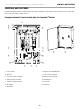
8. Connect Generator Ground to ground bar.
Torque to 35-45 in-lbs.
9. Connect Load bars L1 and L2 to distribution panel.
Torque to 275 in-lbs.
10. Pull NEUTRAL from ATS to distribution panel. Pull GROUND
from ATS to distribution panel.
CAUTION
Remove bond from distribution panel if installed.
INSTALLATION
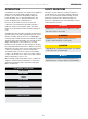
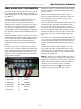
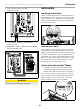
Low Voltage Control Relays
The aXis Controller
TM
ATS has two low voltage relays that can be
used to manage the load of air conditioners or other devices that
utilize low voltage controls. The ATS’s two low voltage relays are
called AC1 and AC2 and are found on the aXis control board as
shown in the picture below.
AC 2
Pin 1 Pin 2 Pin 3 Pin 1 Pin 2
AC 1
CONNECTING TO AC1 AND AC2
For air conditioner or other low voltage controls, route your low
voltage wiring into the ATS using code appropriate conduit and
fittings. Connect the wiring to pin 1 and pin 2 of either AC1 or AC2
as shown in the diagram above. Please note that AC2 has three
pins available. Pin 3 of AC2 is only used when this ATS is being
wired to a non-aXis Controller
TM
HSB. In that scenario, Pin 1 and
Pin 3 of AC2 become the two-wire start signal for the non-axis
HSB and AC2 cannot be used to manage a load.
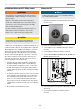
Settings on the aXis Controller
TM
Module
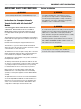
1. On the aXis control board, set the two circular pots that
are located to the right of the DIP switches to match the
maximum power output of the generator for your fuel type.
1st pot (left pot) is 10’s value, 2nd pot (right pot) is 1’s value, do
not go over generator rating. If wattage rating of generator falls
between settings choose the next lower value; i.e. generator
rating is 12,500W, set pots to 1 and 2 for 12,000W.
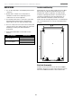
NO
1 2 3 4 5 6 7 8 9 10 11 12
0
1
2
3
4
5
6
7
8
9
0
1
2
3
4
5
6
7
8
9