
Installation Guide

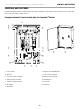


102006 - AUTOMATIC TRANSFER SWITCH WITH aXis CONTROLLER™ MODULE
INSTALLATION
11
NOTICE
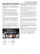
All DIP switches are set to ON by default from the factory.
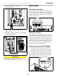
2. Verify the DIP switches are set for your installation. Adjust as
needed.
DIP Switch Settings
Switch 1. Load Module 1 Lockout
– On= Load Module 1 is being managed. Load Module 1 is the
lowest priority of the 4 load modules. This load will be turned
off first as the ATS manages the home’s load.
– Off= Load module 1 will stay off during HSB power.
Switch 2. Load Module 2 Lockout
– On= Load Module 2 is being managed.
– Off= Load module 2 will stay off during HSB power.
Switch 3. Load Module 3 Lockout
– On= Load Module 3 is being managed.
– Off= Load module 3 will stay off during HSB power.
Switch 4. Load Module 4 Lockout
– On= Load Module 4 is being managed. Load Module 4 is the
highest priority of the 4 load modules. This load will be turned
off last as the ATS manages the homes load.
– Off= Load module 4 will stay off during HSB power.
Switch 5. Frequency Protection.
– On= All managed loads will be turned off when if the HSB
frequency drops below 58 Hz.
– Off= All managed loads will be turned off when if the HSB
frequency drops below 57 Hz.
Switch 6. Spare. Not used at this time. Switch position does not
matter.
Switch 7. Power Management
– On= ATS is managing the homes load.
– Off= ATS has disabled power management.
Switch 8. PLC vs. Two Wire Communication
– On= ATS will control HSB startup and shutdown through PLC.
This is the preferred method of communication however it
requires the HSB to be an aXis controlled HSB.
– Off= ATS will control the start of the HSB using the AC2 Relay.
In this setting the AC2 can not be used to manage a load. Pins
1 and 3 of the AC2 connector will be used for the HSB startup
signal.
Switch 9. Test HSB with Load
– On= Test occurs with load.
– Off= Test occurs without load.
Switch 10. Master/Slave
– On= This ATS is the primary or only ATS. <- most common.
– Off= This ATS is being controlled by a different aXis
controller™ ATS. Used for installations that require two ATS
boxes (i.e. 400A installations).
Switch 11. Exercise Test
– On= Exercise tests will occur per the schedule that is
programmed into the aXis controller.
– Off= Exercise tests are disabled.
Switch 12. Time delay for HSB to accept load.
– On= 45 seconds.
– Off= 7 seconds.
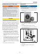
3. Have authorized utility personnel reconnect the utility meter
to the meter socket.
4. Verify voltage at utility circuit breaker.
5. Turn on utility circuit breaker.
6. ATS aXis Controller
TM
module will begin boot up process.
Allow ATS aXis Controller
TM
module to fully boot up
(approximately 6 minutes).
7. Home should be fully powered at this point.
WIFI Setup Method
1. Use a WiFi enabled device (laptop, smart phone, tablet, etc.)
in near proximity to the ATS.
2. Search and Connect to network name (SSID) “Champion
HSB”. The password for the network is located on a decal on
the deadfront of the ATS.
3. After connecting, open your device’s web browser. Many
times the Champion aXis Controller
TM
Home Standby
Generator Settings Page will autoload however if that is not
the case, refresh the browser or change the web address to
anything.com. As your device attempts to reach the internet
the WiFi module in the ATS will redirect your browser to the
Champion aXis Controller
TM
Home Standby Generator Settings
Page.