
Installation Guide
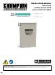

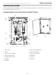

102006 - AUTOMATIC TRANSFER SWITCH WITH aXis CONTROLLER™ MODULE
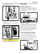
PANEL BOARD SAFETY INFORMATION
7
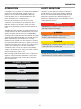
PANEL BOARD SAFETY INFORMATION
As of January 1, 2017, enhanced UL 67 safety requirements took
effect, applying to all panel boards and load centers with service
equipment applications in accordance with the National Electrical
Code, NFPA 70.
To comply, any single service disconnect panel board or load
center must have provisions such that, when the service
disconnect is opened, no person in the field servicing the
equipment load side can make accidental contact to live circuit
parts. Barriers to protect against unintended contact shall be
constructed in such a way that they are easily installable and
removable without contacting or damaging bare or insulated live
parts. The barrier could be installed on the ARM, panel board or
load center.
The battery(s) might be discharged to a level that is too low to re-
charged with this charger (battery voltage below 6V). If this is the
case, the batteries will need to be charged individually. Remove
all battery cables from the batteries and follow the battery
manufacturers’ instructions on properly servicing/charging the
batteries.
Be careful to avoid corrosion on the battery post(s). Corrosion
can have the effect of creating an insulation between the post(s)
and the cable(s), this will severely affect the performance of the
battery. Follow battery manufacturers’ instructions on proper
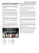
maintenance, service or replacement. The correct wire lands are
read left to right, 6 land points;
1. Wire land #1 Ground G (GREEN)
2. Wire land #2 L1 P (PINK)
3. Wire land #3 N W (WHITE)
4. Wire land #4 NOT CONNECTED EMPTY
5. Wire land #5 B- B (BLACK)
6. Wire land #6 B+ R (RED)
A 120VAC circuit must be installed for battery charging. From ATS
fuse block or distribution panel install L1 and N to Wire land # 2
and #3 respectively.
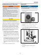
Automatic Transfer Switch (ATS) Service Entrance models
Refer to the Champion ATS instruction guide enclosed with each
unit for information related to installation, operation, service,
trouble shooting and warranty.
The most reliable and convenient method to transfer power is with
an automatic transfer switch (ATS). The ATS will automatically
disconnect the home from the utility power prior to the HSB
functioning (see NEC 700, 701 and 702). Failure to disconnect the
home from the utility with an approved UL listed ATS can result
in damage to the HSB and can also cause injury or death to utility
power workers who may receive electrical back-feed from the
HSB.
ATS includes sensors to detect when a power failure (utility lost)
occurs. These sensors trigger the ATS to disengage the home from
the utility power. When the HSB reaches the proper voltage and
frequency, the ATS will automatically transfer generator power to
the home.
The ATS module continues to monitor the utility source for the
return of utility power. When the utility power returns, the ATS
disengages the home from generator power and re-transfers the
home to utility power. The HSB is now off line and will shut down-
-returning to the standby mode.
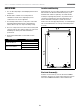
NEMA 3R – This type of enclosed ATS is similar to the indoor box,
except that it is a weatherproof enclosure and required for exterior
installations by code. The enclosure has knockouts on the bottom
and side, and requires water tight connections when installed
outside per code. This enclosure can also be used inside.
The HSB Generator Exercise mode
allows for automatic
operation at specific times (set by the installer or owner).