MDS-6A Integrated Multi-ZZone Controller INSTALLATION MANUAL AND USER’S GUIDE TM MDS-6A
MDS-6A TABLE OF INSTALLATION MANUAL CONTENTS SECTION 1 Introduction 1.1 Feature Overview . . . . . . . . . . . . . . . . . . . . . . . . . . . .5 1.2 MDS-6A Specifications. . . . . . . . . . . . . . . . . . . . . . . . .6 1.3 MDS-6A Front Panel Adjustments . . . . . . . . . . . . . . . .7 SECTION 2 Connections and Settings 2.1 System Overview . . . . . . . . . . . . . . . . . . . . . . . . . . . .8 2.2 Wiring MCS Controllers to the MDS-6A . . . . . . . . . . . .9 2.3 Source and IR Connections . . . . .
MDS-6A INSTALLATION MANUAL IMPORTANT SAFETY INFORMATION Read Information—All the safety and operating information should be read before the appliance is operated. Follow Information—All operating and use information should be followed. Retain Information—The safety and operating information should be retained for future reference. Heed Warnings—All warnings on the appliance and in the operating instructions should be heeded.
MDS-6A INSTALLATION MANUAL Power Cord Protection—A.C.Power supply circuits should be routed by a certified electrician only, in accordance with the NEC standards. Telephones—Avoid using a telephone (other than a cordless type) during an electrical storm. There may be a remote risk of electrical shock from lightning. Do not use a telephone to report a gas leak if the leak is in the vicinity of the Channel Plus electronic equipment because of risk of fire or explosion.
MDS-6A INSTALLATION MANUAL SECTION 1 - INTRODUCTION 1.1 - FEATURE OVERVIEW 6 Sources / 6 Zones The MDS-6A enables you to independently listen to and control up to six different audio sources (i.e. Tuner, CD, Tape Deck - and the audio signals from your VCR, DVD, and Satellite Receiver) in six distinct listening areas or “zones”. 12 Channel x 40 WPC Power Amplifier The MDS-6A features 12 channels of amplification capable of delivering 40 watts per channel into 8 ohms.
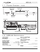
MDS-6A 1.1 - FEATURE OVERVIEW - INSTALLATION MANUAL CONT. Zone ON / OFF Status LEDs Music-on-Hold Volume Level Adjustment Power LED MDS-6A TM Page/Doorbell Volume Level Adjustment IR Activity Indicator LED Power Switch Modular Speaker Connectors Figure 1 Source Inputs IR Emitter Outputs Page/Doorbell/ Music on Hold Zone Keypad Inputs 1.2 - MDS-6A SPECIFICATIONS Source Inputs Music On Hold Output INPUT SENSITIVITY......................................................0-2V RMS INPUT IMPEDANCE.
MDS-6A INSTALLATION MANUAL 1.3 - MDS-6A FRONT PANEL ADJUSTMENTS Music-On-Hold Output Gain Adjustment As shown on page 6, this potentiometer adjusts the gain of the Music-On-Hold signal (Source #1) going to the Music-On-Hold input of a phone system or other communication device. Page/Doorbell Input Gain Adjustment Adjusts the input level of the Page and Doorbell signal. Zone Status LED Indicators SOLID Indicates the zone is on. Power LED Indicates the MDS-6A is powered up.
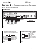
MDS-6A SECTION 2 - CONNECTIONS AND 2.1- SYSTEM OVERVIEW INSTALLATION MANUAL SETTINGS SYSTEM OVERVIEW WARNING REPLACE FUSE WITH SAME TYPE AND RATING ONLY POWER INTERT E K T4AL TYPE FUSE CM C US L I ST E D 9700721 MODEL: MDS-6A RISK OF ELECTRIC SHOCK MUSIC DISTRIBUTION SYSTEM DO NOT OPEN WARNING: DO NOT REMOVE COVER. AVIS NO USER SERVICEABLE PARTS INSIDE. REFER SERVICE TO CHANNEL PLUS RISQUE DE CHOC ELECTRIQUE SERVICE TECHNICIAN.
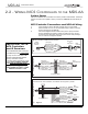
MDS-6A INSTALLATION MANUAL 2.2 - WIRING MCS CONTROLLERS TO THE MDS-6A System Specs Each of the MDS-6A’s Zone Controller RJ-45 Jacks provides 12VDC/300mA. These Zone Keypad connections are capable of driving a maximum of TWO MCS Controllers per zone. MCS Controller Connections and MDS-6A Wiring 1. 2. CAT-5 should be used for all MCS Controller wire runs (max 500ft). MCS Controller wire runs can be terminated directly to RJ45 connectors and then plugged into the MDS-6A.
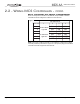
MDS-6A 2.2 - WIRING MCS CONTROLLERS - INSTALLATION MANUAL CONT. MCS Controller DIP Switch Configuration When connecting MCS Controllers to the MDS-6A, all dip switches on all MCS Controllers should be configured to reflect their correct Zone ID.
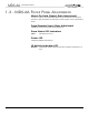
MDS-6A INSTALLATION MANUAL 2.3 - SOURCE AND IR CONNECTIONS Source and IR Connections The MDS-6A has six pairs of line-level audio inputs for the connection of up to six audio sources. Each audio source has a corresponding source-specific IR output for the connection of IR emitters. Source-specific IR outputs allow multiple sources of the same make and model to be controlled independently. The MDS-6A also has an IR ALL port that can be used to control other system components.
MDS-6A INSTALLATION MANUAL SECTION 3 - TROUBLESHOOTING 3.1 - MCS CONTROLLER OPERATION POSSIBLE SOLUTION SYMPTOM POSSIBLE CAUSE MCS Controller totally inoperative (no functions, no LEDs). 1. +12V and/or GND wires are not terminated correctly. 1. Confirm connections 2. Max number of keypads per Zone or MDS-6A exceeded 2. Confirm load 1. RS485+/- wires are terminated incorrectly 1. Confirm connections 2. MCS Controller dip switches are incorrect 2.
MDS-6A INSTALLATION MANUAL 3.2 - INFRARED SYMPTOM POSSIBLE CAUSE POSSIBLE SOLUTION No IR pass-through from IR Receiver. 1. IR Receiver not connected 1. Confirm IR Receiver Connection Activity LED on MDS-6A flickers constantly or continuously lit. 1. IR flooding 1a. Shade IR window with hand. If LEDs cease to flicker or go off, flooding due to ambient light may be the cause. 1b. Move IR Receiver away from light source, or cover inside of IR window with a small piece of plain white paper.
MDS-6A INSTALLATION MANUAL NOTES: Page 14 © Channel Plus, Inc. 2004 • All rights reserved.
MDS-6A INSTALLATION MANUAL NOTES: © Channel Plus, Inc 2004 • All rights reserved.
MDS-6A INSTALLATION MANUAL Limited Warranty Linear LLC warrants this product to be free from defects in material and workmanship for 2 years. The time period will be measured using the date code labeled on the product. Linear LLC is not responsible for damage to the product resulting from the buyer's improper handling, stocking or warehousing of the product. Any implied warranty arising from the sale of the product including implied warranties of merchantability and fitness for purpose are limited.