463251914 during assembly, please call 1-888-430-7870.
TABLE OF CONTENTS THIS GRILL IS FOR OUTDOOR USE ONLY. For Your Safety. . . . . . . . . . . . . . . . . . . . . . . . . . . . . . . . 2 Use and Care . . . . . . . . . . . . . . . . . . . . . . . . . . . . . . . 3-5 Limited Warranty . . . . . . . . . . . . . . . . . . . . . . . . . . . . . . 6 Parts List . . . . . . . . . . . . . . . . . . . . . . . . . . . . . . . . . . . 12 WARNING Failure to follow all manufacturer’s instructions could result in serious personal injury and/or property damage.
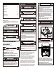
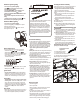
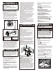
LP Cylinder Filling USE AND CARE LP Cylinder Removal, Transport and Storage •Turn OFF all control knobs and LP cylinder valve. Turn coupling nut counterclockwise by hand only - do not use tools to disconnect. Loosen cylinder screw beneath bottom shelf or disconnect other retention means, then lift LP cylinder up and and out of cart. Install safety cap onto LP cylinder valve. Always use cap and strap supplied with valve.
WARNING • Do not use grill until leak-tested. • If a leak is detected at any time, STOP! • If you cannot stop a gas leak by closing the LP cylinder valve leave area and call your fire department! Leak Testing Valves, Hose and Regulator 1.Turn all grill control knobs to OFF. 2.Be sure regulator is tightly connected to LP cylinder. 3.Completely open LP cylinder valve by turning hand wheel counterclockwise. If you hear a rushing sound, turn gas off immediately. There is a major leak at the connection.
Sideburner Ignitor Lighting • Do not lean over grill while lighting. 1. Turn OFF all gas burner control valves. 2. Turn ON gas at LP cylinder. 3. To ignite SIDEBURNER, open sideburner cover. 4. Turn sideburner knob to the position. 5. Push and hold ELECTRONIC IGNITOR button until the burner lights. 6. Once burner has ignited, turn knob to desired setting. 7. If sideburner does not light, turn knob to OFF, wait 5 minutes, then repeat lighting procedure.
LIMITED WARRANTY This warranty only applies to units purchased from an authorized retailer. Manufacturer warrants to the original consumer-purchaser only that this product shall be free from defects in workmanship and materials after correct assembly and under normal and reasonable home use for the periods indicated below beginning on the date of purchase*.
ÍNDICE DE MATERIAS ESTA PARRILLA SOLO SE PUEDE USAR EN EXTERIORES. ADVERTENCIA PELIGRO ADVERTENCIA • No es posible apagar los fuegos provocados por la grasa cerrando la tapa. Por razones de seguridad, las parrillas tienen aberturas de ventilación. • No use agua para apagar los fuegos provocados por la grasa. Esto puede ocasionar lesiones. Si surge un fuego provocado por la grasa, cierre las perillas y el tanque de gas.
USO Y MANTENIMIENTO Remoción, transporte y almacenamiento del tanque de gas propano •CIERRE todas las perillas de control y la válvula del tanque. Gire la tuerca de unión en sentido contrario a las agujas del reloj, a mano solamente; no use herramientas para desconectarla. Afloje el tornillo, ubicado debajo de la repisa, o desconecte el dispositivo de retención del tanque, luego levante el tanque de gas para sacarlo del carrito. Instale la tapa de seguridad en la válvula del tanque de gas.
ADVERTENCIA • No use la parrilla sin antes haber verificado que no tenga fugas. • En caso de detectar una fuga en cualquier momento, ¡DETÉNGASE ! • Si no puede detener una fuga de gas cerrando la zona baja vavle del tanque de gas y llame a los bomberos. Prueba para detectar fugas de las válvulas, las mangueras y el regulador 1.Cierre todas las perillas de control de la parrilla. 2.Cerciórese de que el regulador esté bien conectado al tanque de gas. 3.
Encendido del quemador lateral con el encendedor • No se incline sobre la parrilla cuando la esté encendiendo. 1. Gire todas las perillas de control de las válvulas del quemador a la posición de APAGADO (OFF) . 2. ABRA el gas en el tanque o en la fuente de suministro. 3. Para encender el quemador lateral, abra la tapa del mismo. 4. Para encender el quemador lateral, gire la perilla a la graduación . 5. Pulse y mantenga pulsado el botón de encendido ELECTRÓNICO hasta que se encienda el quemador. 6.
GARANTÍA LIMITADA Esta garantía es válida únicamente para las unidades adquiridas de los distribuidores autorizados. El fabricante le garantiza únicamente al consumidor-comprador original, que este producto no presentará defectos de mano de obra ni de materiales por el período indicado a continuación, contado desde la fecha de compra*, si se arma correctamente y se usa en el hogar, en condiciones normales y razonables.
PARTS LIST Key Key Qty Description 1 1 TOP LID 2 2 3 4 5 6 Qty Description BEZEL, F/ LID HANDLE 40 41 1 1 LOWER BACK PANEL CABINET SHELF/ DIVIDER 1 HANDLE F/ TOP LID 42 1 CENTER CART DIVIDER 1 2 43 44 1 1 GROMMET BOTTOM SHELF 4 LOGO PLATE, TEMP GAUGE RUBBER BUMPER, ROUND, W/ HARDWARE, F/ TOP LID RUBBER BUMPER, LID 45 46 1 2 TANK SCREW, F/ BOTTOM SHELF CASTER, LOCKING 7 1 FIREBOX 8 2 COOKING GRATE 47 48 2 1 CASTER, FIXED HARDWARE F/ TOP LID ASSEMBLY 9 1 WARMING RACK 10
LISTA DE PARTES Clave Cant. Descripción 1 1 TAPA SUPERIOR 2 2 EXTREMO DEL ASA, TAPA SUPERIOR 3 4 1 1 ASA DE LA TAPA SUPERIOR 5 2 6 4 PLACA DEL LOGOTIPO, CON MEDIDOR DE TEMPERATURA TOPE DE CAUCHO, REDONDO, c. HERRAJE, TAPA SUPERIOR TOPE DE CAUCHO, TAPA SUPERIOR 7 1 CÁMARA DE COMBUSTIÓN 8 2 PARRILLA DE COCCIÓN 9 10 1 4 REJILLA PARA CALENTAR ALIMENTOS 11 2 12 2 Clave Cant.
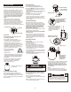
PARTS DIAGRAM/ VISTA ESQUEMÁTICA DE PIEZAS #1 #48 #4 #6 #5 #50 #9 #13 #18 #2 #3 #8 #10 #11 #11 #49 #12 #12 #20 #19 #29 #22 #28 #7 #16 #17 #36 #24 #25 #23 #26 #15 #32 #14 #29 #33 #31 #41 #28 #27 #36 #30 #40 #21 #43 #37 #36 #34 #51 #39 #37 #27 #35 #38 #36 #45 #46 #47 #42 #44 14
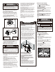
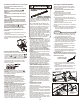
ASSEMBLY/ ARMADO 1 1ST 2ND #47 #46 3RD Caster pin Clavija para la rueda #44 2 #38 A A A A 1/4-20x1/2" Screw Qty. 6 Tornillo de 1/4-20 x 1/2" Cant.
3 #40 A A A A 1/4-20x1/2" Screw Qty. 5 Tornillo de 1/4-20 x 1/2" Cant. 5 A A 4 B A B #10-24x3/8" Screw Qty. 3 Tornillo No.10-24x3/8" Cant. 3 A A B #8x3/8" self-tapping Screw Qty. 2 Tornillo autorroscante No. 8x3/8" Cant.
5 A #10-24x3/8" Screw Qty. 4 Tornillo No.10-24x3/8" Cant. 4 #41 A A A A 6 A #30 A 1/4-20x1/2" Screw Qty. 1 Tornillo de 1/4-20 x 1/2" Cant.
7 #31 A A B A 1/4-20x1 ½" Screw Qty. 2 Tornillo de 1/4-20 x 1½" Cant. 2 B #8x3/8" self-tapping Screw Qty. 1 Tornillo autorroscante No. 8x3/8" Cant.
9 A A B A A B B A B 1/4-20x1½" Screw Qty. 4 Tornillo de 1/4-20 x 1½" Cant. 4 A B B Fiber Washer Qty. 4 Arandela de fibra Cant.
11 #24 A #23 #10-24x3/8" Screw Qty. 4 Tornillo No.10-24x3/8" Cant. 4 A A A A B #23 B E E 1/4-20x1½" Screw Qty. 1 Tornillo de 1/4-20 x 1½" Cant. 1 C D C F D F C #24 #8x3/8" self-tapping Screw Qty. 2 Tornillo autorroscante No. 8x3/8" Cant. 2 D Large Flat Washer Qty. 2 Arandela plana grande Cant. 2 E 1/4" Nut Qty. 2 Tuerca de 1/4" Cant. 2 F C E E D B F 1/4-20x1/2" Screw Qty. 2 Tornillo de 1/4-20 x 1/2" Cant.
12 #15 A #14 #10-24x3/8" Screw Qty. 4 Tornillo No.10-24x3/8" Cant. 4 A A A A B B E #14 E C D C 1/4-20x1½" Screw Qty. 1 Tornillo de 1/4-20 x 1½" Cant. 1 D F F #15 C #8x3/8" self-tapping Screw Qty. 2 Tornillo autorroscante No. 8x3/8" Cant. 2 D Large Flat Washer Qty. 2 Arandela plana grande Cant. 2 E F E D C F B E 1/4" Nut Qty. 2 Tuerca de 1/4" Cant. 2 F 1/4-20x1/2" Screw Qty. 2 Tornillo de 1/4-20 x 1/2" Cant.
13 1ST Remove screws and washers Retire los tornillos y arandelas 2ND #26 A #8-32x3/8" Screw Qty. 2 Tornillo No. 8-32x3/8" Cant.
14 #19 #20 1ST A #26 A Wing Nut Qty. 1 Tuerca de mariposa Cant.
15 #17 A A A A A #8-32x3/8" Screw Qty. 4 Tornillo No. 8-32X3/8" Cant. 4 B #8-32 Nut Qty. 4 Tuerca de No. 8-32 Cant.
17 2ND PRESS OPRIMA #35 1ST 25
18 1ST A #8-32x1/4" Screw Qty. 4 Tornillo No. 8-32x1/4" Cant. 4 A A A A A 2ND A A #8-32x1/4" Screw Qty. 4 Tornillo No. 8-32x1/4" Cant.
19 Note: Remove caps from trough supports (8 places) Nota: Retire las tapas de apoyos cilindro (8 plazas) Trough support Soporte de la cuba Trough pins Clavija de la cuba #49 20 #8 27
21 #9 28
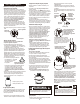
22 1ST LP Cylinder (not included) Tanque de gas propano (no viene incluido) 2ND #45 CAUTION ADVERTENCIA Una vez que el tanque haya quedado instalado, la válvula del tanque debe quedar orientada hacia la parte delantera del carrito. Si no se instala correctamente el tanque, se puede dañar la manguera de gas durante el suministro, lo que puede ocasionar el riesgo de incendio. Cylinder valve must face to front of cart once tank is attached.
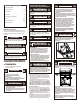
EMERGENCIES: If a gas leak cannot be stopped, or a fire occurs due to gas leakage, call the fire department. Emergencies Possible Cause Prevention/Solution Gas leaking from cracked/cut/burned hose. • Damaged hose. •Turn off gas at LP cylinder or at source on natural gas systems. Discontinue use of product and replace valve/hose/regulator. Once valve/hose/regulator replaced conduct complete leak check per manual. Gas leaking from LP cylinder. • Mechanical failure due to rusting or mishandling.
Troubleshooting (continued) Possible Cause Prevention/Solution • Out of gas. • Check for gas in LP cylinder. • Excess flow valve tripped. • Turn off knobs, wait 30 seconds and light grill. If flames are still low, turn off knobs and LP cylinder valve. Disconnect regulator. Reconnect regulator and leak-test. Turn on LP cylinder valve, wait 30 seconds and then light grill. • Vapor lock at coupling nut/LP cylinder connection. • Turn off knobs and LP cylinder valve. Disconnect coupling nut from cylinder.
CASOS DE EMERGENCIA: Si no se puede detener una fuga de gas, o si ocurre un incendio debido a una fuga de gas, llame a los bomberos. Emergencias Causas probables Medidas de prevención / solución Fugas de gas de mangueras agrietadas, cortadas o quemadas. • Manguera dañada. • Cierre el gas en el cilindro o en la fuente de los sistemas de gas natural.Deje de utilizar el producto y vuelva a colocar la válvula / la manguera / el regulador.
Resolución de problemas (continuación) Problema Caída repentina del flujo de gas o llama reducida. Llamas que se apagan. Causas probables Medidas de prevención / solución • Se acabó el gas. • Verifique que el tanque de gas esté cargado. • Se activó la válvula por sobrecarga de gas. • Cierre las perillas, espere 30 segundos y encienda la parrilla. Si las llamas siguen siendo bajas, cierre la perilla y la válvula del tanque de gas. Desconecte el regulador.
NOTES/ NOTAS 34