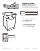
PRODUCT GUIDE MODEL 463240613 Char-Broil Modular Stove Top Cart IMPORTANT: Fill out the product record information below. Serial Number See rating label on grill for serial number. Date Purchased For support and to register your grill, please visit us at www.charbroil.com If you have questions or need assistance during assembly, please call 1-800-241-7548.
TABLE OF CONTENTS DANGER For Your Safety . . . . . . . . . . . . . . . . . . . . . . . . . . . . . . . . . . . . 2-3 Use and Care. . . . . . . . . . . . . . . . . . . . . . . . . . . . . . . . . . . . . 4-10 Limited Warranty. . . . . . . . . . . . . . . . . . . . . . . . . . . . . . . . . . . . 12 Parts List. . . . . . . . . . . . . . . . . . . . . . . . . . . . . . . . . . . . . . . . . . 13 Parts Diagram. . . . . . . . . . . . . . . . . . . . . . . . . . . . . . . . . . . . . . 14 Assembly . . . . . . .
WARNING CALIFORNIA PROPOSITION 65 1. Combustible by-products produced when using this product contains chemicals known to the State of California to cause cancer, birth defects, or other reproductive harm. 2. This product contains chemicals, including lead and lead compounds, known to the State of California to cause cancer, birth defects or other reproductive harm. Wash your hands after handling this product.
USE AND CARE DANGER • NEVER store a spare LP cylinder under or near the appliance or in an enclosed area. • Never fill a cylinder beyond 80% full. • An over filled or improperly stored cylinder is a hazard due to possible gas release from the safety relief valve. This could cause an intense fire with risk of property damage, serious injury or death. • If you see, smell or hear gas escaping, immediately get away from the LP cylinder/appliance and call your fire department.
LP Cylinder Exchange Connecting Regulator to the LP Cylinder •Many retailers that sell grills offer you the option of replacing your empty LP cylinder through an exchange service. Use only those reputable exchange companies that inspect, precision fill, test and certify their cylinders. Exchange your cylinder only for an OPD safety feature-equipped cylinder as described in the "LP Cylinder" section of this manual. 1.LP cylinder must be properly secured onto grill. (Refer to assembly section.
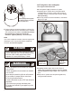
Leak Testing Valves, Hose and Regulator 1.Turn all grill control knobs to OFF. 2.Be sure regulator is tightly connected to LP cylinder. Str aig ht Hold coupling nut and regulator as shown for proper connection to LP cylinder valve. 3.Completely open LP cylinder valve by turning hand wheel counterclockwise. If you hear a rushing sound, turn gas off immediately. There is a major leak at the connection. Correct before proceeding. 4.
Safety Tips WARNING For Safe Use of Your Grill and to Avoid Serious Injury: • Do not let children operate or play near grill. • Keep grill area clear and free from materials that burn. • Do not block holes in sides or back of grill. • Check burner flames regularly, through viewing ports. • Use grill only in well-ventilated space. NEVER use in enclosed space such as carport, garage, porch, covered patio, or under an overhead structure of any kind. • Do not use charcoal or ceramic briquets in a gas grill.
WARNING Turn controls and gas source or tank OFF when not in use. CAUTION If ignition does NOT occur in 5 seconds, turn the burner controls OFF, wait 5 minutes and repeat the lighting procedure. If the burner does not ignite with the valve open, gas will continue to flow out of the burner and could accidently ignite with risk of injury. Stove Top burner Match Lighting 1. Turn all burner control valves to the (OFF) position. 2. Open lid and leave open. Turn ON gas at LP cylinder. 3.
CAUTION SPIDER ALERT! SPIDER AND WEBS INSIDE BURNER If your griddle/stove top is getting hard to light or the flame is weak, check and clean the venturis and burners. • Stainless steel surfaces: To maintain your grill’s high quality appearance, wash with mild detergent and warm soapy water and wipe dry with a soft cloth after each use. Baked-on grease deposits may require the use of an abrasive plastic cleaning pad. Use only in direction of brushed finish to avoid damage.
Cleaning the Burner Assembly Follow these instructions to clean and/or replace parts of burner assembly or if you have trouble igniting stove top. 1. Turn gas OFF at control knobs and LP cylinder. 2. Remove screws that hold orifice holder with the burner venturi. Figure A 3. Remove cooking grate. 4. Remove wing nuts from inside cart to disengage it. Figure B 5. Carefully lift up the burner enough to expose the electrode wire. Detach wire from electrode underneath the burner 6.
NOTES 11
LIMITED WARRANTY This warranty only applies to units purchased from an authorized retailer. Manufacturer warrants to the original consumer-purchaser only that this product shall be free from defects in workmanship and materials after correct assembly and under normal and reasonable home use for the periods indicated below beginning on the date of purchase*.
PARTS LIST Key Qty Description NOT Pictured A 1 TOP LID … 1 NATURAL GAS ORIFICE KIT B 4 RUBBER BUMPER, ROUND … 1 CASTER PIN C 1 FIREBOX … 1 HARDWARE PACK D 1 BURNER … 1 ASSEMBLY MANUAL, ENGLISH E 1 ELECTRODE, F/ BURNER … 1 ASSEMBLY MANUAL, SPANISH F 1 CONTROL PANEL G 1 HOSE VALVE REGULATOR ASSEMBLY H 1 BEZEL, F/ CONTROL KNOB I 1 CONTROL KNOB J 1 IGNITER SWITCH MODULE K 2 TOP LID HINGE, STRAIGHT L 2 TOP LID HINGE, BENT M 1 1 GRATE N LEFT SIDE CART PAN
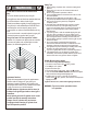
PARTS DIAGRAM C A M F B G E D K L CC W I H J V AA O Y Z BB P R N Q T X U 14 S
ASSEMBLY 1 Place bottom shelf upside down. Insert Caster Pin into the caster mounting plate to lock it in place, shown A. Spin the casters clockwise into the threads on the bottom shelf until secure. Remove the Caster Pin and repeat for remaining casters. Make sure the two locking casters are secured at the rear and the non-locking casters are secured at the front. After all 4 casters are secured remove the Caster Pin and save for future maintenance.
3 Insert front brace between cart panels. Make sure door hinge pin is on the top side and facing the front. Secure front brace using two 1/4-20x1/2” screws on each side. Front brace 1/4-20x1/2" screw Right side panel Left side panel Rear 4 This step requires two people to lift and position stove top onto cart. Carefully lower the stove top onto the cart, Attach stove top to cart with four 1/4-20x1/2" screws. Make sure the regulator and ignitor wires are hanging inside the cart.
5 Connect the wire from burner electrode into the back of Electronic ignition module, positions 1. Connect the two wires [(a) and (b)] from switch wiring harness into the back of Electronic ignition module. NOTE: Switch terminals are larger than electrode terminal and should only be installed in location shown as (a),(b). Release cap and nut from electronic ignition module. Attach Electronic ignition module to front brace with the nut. Insert AAA battery into module, negati v e (-) end first.
7 Attach tank exclusion wire to back panel and front brace using two #8-32x3/8" screws and #8-32 nuts. Back panel #8-32x3/8" screw Tank exclusion wire #8-32 nut Note: some parts omitted for clarity of illustration #8-32 nut Front brace #8-32x3/8" screw 8 Attach door handle to door using two #10-24x3/8" screws.
9 10 Place cooking grate on the stove top as shown, align grate legs into matching slots in the stove top. Insert hinge pin on bottom of door into hole in bottom shelf. Press upper hinge pin in front brace, align hinge hole on top of door and release hinge pin into door.
LP CYLINDER IS SOLD SEPARATELY. Fill and leak check the cylinder before attaching to grill and regulator (see Use & Care section). Once cylinder has been filled and leak checked, place cylinder into hole in bottom shelf. Make sure cylinder valve is facing front of grill. Secure cylinder with cylinder screw under bottom shelf. See Use & Care section of this manual to perform the burner Flame Check and for important safety instructions before using.
Consumer must purchase Natural Gas Conversion Kit 4984619 to convert this grill to natural gas. Use the following instructions instead of instructions found in conversion kit Main Burner Conversion 1 Make sure all Control Knobs are in the OFF position, LP Tank Valve is closed, Tank is disconnected from Regulator and removed from Grill. Remove cooking grates or griddle plate. Your grill may differ from illustration shown. This portion of the manual covers a variety of grill styles.
4 Pull the Burner Control Knob off of Valve Stem. Remove Screws and Washers that secure the Bezel to the Control Panel. Save removed Bezel for converting back to LP Tank Gas. Install new Natural Gas Bezel provided with Kit (see illustration below) in place of old Bezel, on Control Panel and secure using previously removed Screws and Washers. Assure proper alignment with Control Knob before fully tightening.
Natural Gas Hose Conversion 6 Using a wrench, not provided, remove LP Regulator Hose Assembly from Manifold Connection. Save removed LP Manifold Connection for converting back to LP Tank Gas. Your Grill may differ from illustration shown.
WARNING Do not use hard metal piping of any kind to connect this type of grill to natural gas source. Use only hose specified by manufacturer. Using hard metal piping or convoluted metal tubing is an unsafe practice. Movement of the grill can cause breakage of metal pipe. 4. When the quick disconnect socket and the gas hose are connected, a valve in the socket opens automatically to permit full gas flow.
DANGER: If a gas leak cannot be stopped, or a fire occurs due to gas leakage, call the fire department. Emergencies Possible Cause Prevention/Solution Gas leaking from cracked/cut/burned hose. • Damaged hose. • Turn off gas at LP cylinder or at source on natural gas systems. If anything but burned, replace valve/hose/regulator. If burned, discontinue use of product until a plumber has investigated cause and corrections are made. Gas leaking from LP cylinder.
Troubleshooting (continued) Problem Possible Cause Prevention/Solution Burner(s) will not light using ignitor. (See Electronic Ignition Troubleshooting also) ELECTRONIC IGNITION: • No spark, no ignition noise. • See Section I of Electronic Ignition System. • No spark, some ignition noise. • See Section II of Electronic Ignition System. • Sparks, but not at electrode or at full strength. • See Section III of Electronic Ignition System. Burner(s) will not match light.
Troubleshooting - Electronic Ignition Problem (Ignition) Check Procedure Prevention/Solution • Check battery orientation. • Install battery (make sure that “+” and “–” connectors are oriented correctly, with “+” end up and “–” end down.) • Has battery been used previously? • Replace battery with new alkaline battery. • Button assembly not installed properly. • Check to insure threads are properly engaged. Button should travel up and down without binding.
NOTES 28
NOTES 29
NOTES 30
Please register your product online at: Registre su producto en línea en: Veuillez enregistrer votre produit à l'adresse: www.charbroil.com/register (If you register online, you do not need to send in this registration card.) (Si registra en línea, no es necesario enviar esta tarjeta de registro.) (Si vous enregistrez votre produit en ligne, il n'est pas nécessaire d'envoyer la carte d'enregistrement.) PLEASE FILL OUT THIS CARD AND ATTACH A COPY OF YOUR SALES RECEIPT. RETURN IT WITHIN10 DAYS OF PURCHASE.
THANK YOU FOR YOUR RECENT PURCHASE FROM CHECK OUT THESE GREAT FEATURES ON OUR WEBSITE • Valuable product information • Inspiring grilling accessories • Reliable customer support • Delicious recipes and tips from chefs • Exciting events and promotions • And much more! REGISTER YOUR PRODUCT TO RECEIVE A SPECIAL OFFER CHARBROIL.