Thank you for your purchase of this Tachometer Product. This manual explains how to operate your equipment safely and correctly. The manual covers the various different features of the DT-209X. Kindly read this manual thoroughly before operation as it holds important information that will help you fully utilize this unit. Caution warning holds important safety information Reminder: holds important key information for the product. Warning: Laser equipped product.
DT-209X Handheld Digital Laser Tachometer Table of Contents Section I – Handheld Tachometer • • • • • • • • • • • • • • • Description of Parts………………………………………………………………………….………1 Description LCD Display…………………………………………………………………….………3 Unit Selector Switch………………………………………………………………………………….4 Abbreviation of Display Table………………………………………………………………………5 Power Supply…………………………………………………………………………………………6 Measurement Modes………………………………………………………………………………...7 Flow Chart Diagram………………………………………………………………………………….
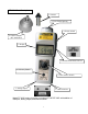
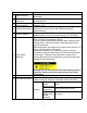
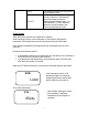
DT-209X Parts Description 4. Contact 6. Laser Beam Opening 9. Power Switch 5. Contact Adapter (DT-ADP-200L) 7. Display 3. Measurement Mode Selector 10. Memory Button 8. Unit Selector Switch 2. Analog Output 1. USB Connector Model DT-209X casing is similar to standard DT-207/DT-205L with addition of USB port, analog output, and selector switch.
Parts 1 2 3 USB Connector Analog Output Connector Measurement Mode Selector Switch 4 Contact Accessories 5 Contact Adapter 6 Laser Beam Opening 7 Display 8 Unit Selector Switch Function Mini-USB connector for PC online measurements and data downloads. 0 to 1-volt analog output connector for pen recorders and other external devices. Slide selector switch for different measuring modes. (USB, Average, STD). Contact attachments for contact measurements.
NonContact 9 10 Power Switch Memory Button Rotation Speed Measurement RPM ON and OFF switch and block separator. For standard and average mode the power switch button is required while taking readings. Failure to press the power button Non- USB Mode will not permit measurements. Pressing the (No cable memory button while holding the power connected) button, allows sample points to be captured. Releasing the power button advances the memory per block.
Unit Selector Switch Multi-mode capability measures RPM, mPM, YPM, FPM, IPM and total meters, yards, feet and inches. NOTE: Selector switch not available in USB mode; all controls are transferred to the software through the USB cable. Measurement method Explanation of Operation Contact measurement requires the contact adapter (DT-ADP-200L) and the proper attachments. NOTE: Make sure that proper position of the knob is selected. For length and linear rate measurements wheel is required to get right ratio.
Operation • The switch selector can be turned clockwise or counter-clockwise depending on which unit of measure is required. • The unit of measure selected on the dial is indicated in the digital display. • Conversion of units –measured values can be automatically converted to the unit selector switch. Limitation: Conversion is limited to the same group of values (example RPM cannot be converted to inches). • Dashes will show on the display when invalid selection is made.
FULL CCCCC Full memory indicator (the unit cannot store additional data) Clear data from memory. Holding memory button for 5 seconds will clear stored data per block in Standard and Average modes. For USB operation, CCCCC indicates deletion of all stored data in the selected measurement mode. Power Supply Each tachometer requires 2 AA batteries to operate. Smart switching feature of the tachometer is active when USB cable is connected. Each tachometer can be bus powered from the USB cable.
NOTE: In USB mode recorded data is downloaded directly to the computer. Auto power off feature of the tachometer is disabled; the supply of power for the unit is coming from the host computer. Measurement Mode The Measurement Mode is changed with the Measurement Mode Selector switch. There are three basic settings USB, Standard and Average. The switch is located on the side of the tachometer (See Description of Parts Section).
• The max, min, average, last and time of measurement can be stored in memory via power button. • The unit can store a maximum of 30 blocks • Each block of data is based from the time the power button was first pressed and then released. Within that time average values are calculated and stored in memory together with the time of measurement. • Only the final set of values are displayed from the tachometer in this mode.
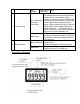
Average Mode Average Mode Press and release the Power button Memory Block 1 “n01” Memory Block 2 “n02” Average values are calculated based from the activation of the power button. (Only average values are available). Memory Block 3 “n03” Memory Block 30 “n30” NOTE: In both Standard and Average Mode, the memory button is pressed to recall memory. It can only give information on the last memory block stored.
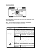
Measuring Methods Rotational speed measurement (Contact RPM) Example: RPM measurement using the cone tip for motor rotation. The contact adapter (DT-ADP-200L) is attached to the tachometer laser opening. There are threads on the adapter assembly for easy installation. Install the contact adapter securely until all the threads are used. To prevent damage do not over tighten. Use the cone tip adapter to read shaft measurements. Slide the tip on the shaft of the tachometer.
Three decimal points will flash on the center of the display when the tachometer is out of range. Speed and Length Measurements Example: Length measurement for amount of materials used. The contact adapter (DT-ADP-200L) is installed on the laser opening. There are threads on the adapter for easy installation. Install the contact adapter securely until all the threads are used. To prevent damage do not over tighten.
Typical measurement update is 1 second. (Using the software the update time can be adjusted as fast as 0.5 second). Things to Remember The rubber portion of the tip accessories (cone tip, funnel tip, FPM wheel) may become hot and may wear out prematurely at high speeds. Press the tachometer firmly on the moving material when using the wheel. Do not go beyond 300mm /min. Non-Contact Measurements Example: Measuring the RPM of a motor shaft.
CAUTION: Do not look into the laser beam opening while in operation. Staring into the laser beam can result to eye damage. The power switch is pressed while taking readings. The Mode Selection Switch is set to either Average or Standard Mode. The display will show “ 0 “ when measurements stop. Measured data is displayed every second (On slower readings less than 60 RPM the display will update approximately every 1- 10 seconds).
Pressing the Power Switch it will show the memory block number where readings will be stored. The block number will flash for a few seconds. (Memory block location is identified by “n” followed by the block number on the LCD display). Standard mode allows 24 blocks; each block can store 10 readings. Note: It is not required to use all the memory blocks; it depends on the application and the usage of this tachometer.
The memory location where the measurement will be stored is shown on the Unit and Measurement section of the LCD display. (“M” followed by the number indicates memory location inside the current block). The memory number will advance automatically as the memory button is pressed each time. The tachometer will stop advancing once 10 memory values are stored (10 memory values per block). To store additional readings the Power Switch is released then pressed again until the number behind “M” changes.
2. Average Mode Average mode is displayed on the LCD screen Pushing the Power Switch will show the memory block number where readings are to be stored. The block number will flash for a few seconds. Average mode allows 30 blocks total, each block is dependent on the time the power switch is first pressed and then released. It is not requried to use all the 30 memory blocks to avail of this mode. It is dependent on the usage of the tachometer.
Releasing the Power Switch will trigger the auto shut off feature to activate. 3. USB Mode The Measurement Mode Selector Switch is set to USB mode (USB mode). The USB mode is displayed on the LCD screen. Please refer to the DT-209X API Section of this manual under USB Mode for additional information. The Power switch and Unit Selector Switch becomes inactive from the DT-209X. All controls are transferred to the host PC. The auto power off feature will not work in USB mode.
LST 1234 RPM MAX 7200 RPM MIN 60 AVE 4500 M1 1234 To recall memory from the DT-209X, the memory button is pressed and then released. The last measured value is displayed. The Memory Button is pressed, and then released. The maximum measured value is displayed. The Memory Button is pressed and then released. The minimum measured value is displayed. The Memory Button is pressed and then released. The Average measured value is displayed. The Memory Button is pressed and then released.
M10 2345 LST 1234 The stored data in the tachometer can be recalled each time the memory button is pressed (M1→M2 etc.). (This is only applicable to the last Memory block used and in Standard Mode). Pressing the Memory Button after M10 will cycle back the process to M1. Only the last memory block is accessible for review. To review all the blocks stored, it is necessary to download the stored data using the USB cable and software. 2.
RPM MIN 60 The Memory Button is pressed and then released. The minimum measured value is displayed. The memory button is pressed and then released. The calculated average value is displayed. AVE 4500 Pressing the memory button cycles back to LST. Note: Only the last Memory block is accessible for review. To review all blocks download data to the DT-209X software Other Functions Memory deletion Pushing the Memory Button for 5 seconds or more clears the last memory block stored in the tachometer.
Clearing all the stored memory blocks requires manual deletion from the tachometer. (Example: To clear 23 blocks of memory requires erasing the memory 23 times.) Memory deletion: The tachometer deletes the last memory block used and shifts down one block at a time, starting from the last going down to the first block stored.
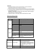
Maximum Values Allowed Unit Full range Non contact 99,999 RPM m/min 3810.0 ft/min 12,500 in 99,999 Yd 99,999 Unit Full range Contact RPM 25,000 yd/min in/min ft m 4617.0 99,999 99,999 99,999 Replacing batteries LO BAT flashes on the LCD display. This indicates that battery needs replacement. For better performance use new Batteries. LO BAT RPM 9999.9 Open battery cover located on the bottom of the tachometer. Insert 2 new batteries; a sticker can be viewed from the case indicating proper polarity.
Specifications Measurement mode Model Standard mode Average mode USB Mode Contact Measurement method Non contact Indicator Contact Non contact Rotational speed Speed Contact Length RPM RPM m/min yd/min ft/min in/min In ft yd m Contact Measurement accuracy Non contact Measurement time Standard Mode Memory function Average Mode USB Communication Analog output function Auto power off feature No USB Cable Connected USB Cable Connected Case material Externals size Mass Ambient temperature of use Ambie
24
25
26
DT-209X API Section Thank you for your purchase of the DT-209X handheld tachometer. Please read this section carefully before using the DT-209X software. This section covers the installation and description of the software for the DT209X. Keep this manual and software safe for future reference. Software Compatibility • • • • • The software is compatible with Windows XP and 2000. Separate USB drivers are provided and can be found in your installation CD.
Observe caution when using this software and mounting the tachometer. Serious damage to equipment is possible when misused. DT-209X API Manual CD Checklists Included in your DT-209X package is a copy of the installation program for the DT-209X operating software. Each CD contains the following files. Folder Driver File name DT209XUSB.dll WindowsXP DT209XUSB.inf DT209XUSB.sys DT209XUSB.dll Windows2000 DT209XUSB.inf DT209XUSB.sys autorun.inf DT209X.exe DT209X init.reg InstMsiA.Exe PC_API InstMsiW.
DT-209X USB Driver Installation: (WINDOWS XP) Included in your package is a USB cable. Attach USB cable to the handheld tachometer and host computer as shown below. Windows will automatically detect the presence of new hardware. Insert software CD and click on “Next”. Windows will search for available drivers. Choose the driver suited for your operating system (Windows XP or Windows 2000).
Click next. Installation process will continue. After installation is completed the following window will be displayed. Click on “Finish” to complete the installation of the DT-209X USB driver. Separate installation is required for computers that will use multiple USB ports. Follow same procedure for each USB port that will be used. Application Software Installation Please follow the following procedures. It is strongly recommended that you close all open programs before installation.
Browse the CD content. Go to PC_API folder Windows installer package Select Windows installer package to start program set up.
DT-209X set up wizard will open. Click “Next>” Choose installation folder where DT-209X program will be stored.
Disk Cost Space availability. Browse • Allows users to select location of the application • Default set up: C: \Program Files\NIDEC-SHIMPO\DT-209X for Windows\ • Select who can access the program (Computers with multiple users). It is recommended to use the default settings for installation of the program for easy access. Click “Next>” to start installation.
Set up wizard will start the installation process. Please allow a few minutes to complete the installation process. Click on “Close” to complete the installation. DT-209X software is ready to use.
DT-209X Application Software Read this section carefully as it holds important information regarding the DT209X software and mode windows operation. From the Start Menu the DT-209X software is listed as NIDEC-SHIMPO. There are two types of operation for the software 1. Download stored information from the handheld tachometer. (Use for Standard and Average Modes). 2. Online measurements, which is available in USB mode.
Main Screen Description 1. Exit – terminates the program and exits the software 2. USB Mode – Online measurement (Note: Make sure that the DT-209X Handheld mode selector switch is set to USB. Failure to do this will not allow communication between host computer and the DT-209X). 3. Standard Memory Mode – Mode option for downloading stored data from the tachometer in Standard Mode. Each memory block is separated by tabs located on the top of the table (Refer to Standard Mode Operation in this section). 4.
5. Time Synchronize - Synchronize time with host computer for generating time stamping reports. To activate this feature click on time synchronize or press ALT + T from the keyboard. After the feature is activated you will notice the time and date window showing the following message. 6. 7. 8. 9. When synchronization is complete the window will return to the time and date format. Standard Memory block Indicator – shows the number of memory blocks used in Standard mode (maximum of 24 memory blocks).
Example: In Non-contact RPM Maximum expected speed is 1,000 RPM. Entering 1,000 in the programmable analog output will scale 1V from 0 to 1000 rpm. (500 rpm will output 0.5 V). If the set rpm exceeded the analog output, it will maintain 1V. If the unit is change it defaults back to maximum value based from the Table of Maximum Values found on page 37. 10. Software display – displays values as measured by the tachometer. Reflects the unit of measure, USB connection status and data points. 11.
Virtual Software LCD Display Troubleshooting USB Communication • If USB communication cannot be establish check USB cable from the tachometer and the host PC. • If after all connections are checked, communication is still inactive, unplug the USB cable from the PC port and plug it back in, Windows should be able to detect the cable. • If after the above conditions are made and still no connection, restart the program.
Unit Selector (Software) Selecting units of measure can be changed easily from the software. Provided on the main window is a virtual copy of the handheld unit selector switch. The selected setting is highlighted in RED; changing the settings would require clicking the mouse and dragging the red highlight to the appropriate setting. The software overrides the Unit Selector Switch from the tachometer. It is completely autonomous; all controls are transferred to the software.
USB Mode Screen USB mode screen display explanation Make sure that the DT-209X handheld tachometer is set to USB mode on the selector switch. Any other settings will not allow the software to recognize the tachometer. 18 1 17 16 2 19 3 4 5 14 6 13 15 12 7 8 10 11 9 1. Main - Return to main screen button (ALT + M) 2. File Save – Save button, opens a Window for saving measured values. Files are saved based on the open set of data on the screen. (ALT + F).
Files are saved in CSV format, which can be opened by spreadsheets. Sample of data opened in Microsoft Excel (USB Mode). Example: Tab of data displayed on the screen in USB mode is the only set of data that will be saved on file, each tab is saved separately. In standard mode all 24 blocks are saved, and in Average Mode all 30 blocks are saved. Sample of data opened in Microsoft Excel (Average Mode).
Sample of data saved in Excel (Standard Mode). 3. Restore – file retrieval button. Open saved file from the computer.
File restore window The letter “R” identifies file restored on the list of data shown from the screen. 4. Start - measurement starts (Only applicable in USB mode). Keystroke shortcut “ALT + S”. If software locks as shown below, please check the mode selector switch. Set switch selector to USB mode. This will allow control back to the software.
5. Print – Print function from the software allows transfer of images displayed from the screen to a local printer. Keystroke shortcut “ALT + P”. 6. Measure – This button allows the creation of a new tab or set of data. It enables the “Start Button” to be active at the beginning of each test. If Measure is not selected, the Start button will not be active. Keystroke shortcut “ALT + M” 7. Clear Block – Deletes selected memory block from the set of online measurements.
Confirmation screen, indicating unselected data will be erased 9. Graph – Opens graph in another window, only available in USB mode. This feature allows observation of actual data while it occurs during measurement test. To return to table of measured values select “Close” located on the middle of the window. 10. Measurement Interval – option to set the measurement interval of the tachometer. This option allows change of measurement interval from 50msec to 5,000msec (5 seconds).
Example: The start trigger is set to 10,000. The tachometer will only start recording values when measurements exceed 10,000. Alarm Whenever an alarm is generated the color of the DT-209X taskbar changes; the computer generates a buzzing sound.
13. Maximum, Minimum, and Mean Value – The maximum, minimum and mean value are displayed based from the recorded data on the table. 14. Records – Displays number of measured data recorded.
15. Start and End – Displays the beginning and the end of measurements. Format: Month/ Day/ Year Time based on 24 Hours: Hour/Min/Seconds 16. Measured Data – measured data are displayed based on their occurrence. 17. Block Tab – block separation of each set of data. Creation of new tab is based from the activation of the measure button. Each memory block can be selected by using the mouse. Block Tab No.7, if an “R” is displayed this means that a set of data is restored or retrieved.
18. Time – Displays synchronized time from the host computer. Format: Month/Day/Year followed by Time: Hour/Minutes Before testing it is advisable to synchronize time with the host computer to update time and date for each record. 19. Software Display – Virtual display of the DT-209X software. It shows updates as measurement are taken. Display includes a USB connector icon to indicate good connection.
USB Mode Graph Screen This section describes the parts and functions of the Graph Screen under USB mode. 5 10 1 3 4 2 9 7 6 8 1. Close – closes the graph screen and moves back the screen to the USB table (Keystroke shortcut ALT + C). 2. Print – prints the graph as displayed from the screen. Size of print is dependent from the settings of the printer. Print button is inactive when measurements are in progress.
4. All – horizontal display control, time axis. Setting Explanation It automatically sets time present while the All measurements are in progress. It is also the time after all measurements are stopped. Setting Limit of the USB main screen Limit The same range setting is set to “All” when Limit is set to 0. 10sec. Selectable time range of each value, optional scroll bars 100sec. are provided for manual view. 300sec. 5. Tab – numbered tabs separate sets of data captured from the tachometer.
Standard Mode Screen Explanation of the Standard mode screen: In this mode data can be downloaded from the DT-209X memory. Memory tab separates each memory block.
1. Main – returns to the main screen (Shortcut keystroke ALT + M). 2. File Save – Downloaded data from the DT-209X is saved in CSV format. (Shortcut Keystroke – ALT + F). Create name of file for the set of measurements. File save is inactive when there is no data available for download. The CSV file can be directly imported to spreadsheets like Microsoft Excel. CSV file is stored by the following formats. "Memory Block No.","Start","Stop","Unit","Memory No.
3. Restore – opens previously saved file. From the screen the restored file has an “R” Tab. (Shortcut Keystroke ALT + R). 4. Download – download function from the software. This allows transfer of stored data from the Tachometer to the software. (Shortcut Keystroke ALT + D). Numbered tabs separates each memory block. 5. Print – print function for the table of values. Size of print is dependent on the attached printer settings. (Shortcut Keystroke ALT + P). 6.
7. Measurement Data – measured values stored in each memory block is displayed. 8. Block Tab – Memory block separation. Each tab corresponds to a set of data stored per memory block. In Standard Mode, there are 24 Blocks or 24 Tabs possible. 9. Scroll – Advances screen values left or right. Useful when screen is minimized. 10. Max, Min, and Ave – quick summary of displayed data. Maximum, minimum and average values are calculated and displayed per set of data displayed from the software screen. 11.
Average Mode Screen Average mode screen description and explanation.
1. Main – returns to the main screen. (Shortcut Keystroke ALT + M) 2. File Save – Saves downloaded data from the tachometer. File save button is inactive when no downloaded data is available. Data are saved in .CSV format, which can be imported directly to spreadsheets like Microsoft Excel. (Shortcut Keystroke ALT + F) File save window The CSV file is stored in this format. "Memory Block No.","Start","Stop","Last","Max.","Min.","Ave.","Unit" 1,03/20/2004 09:17:41,03/20/2004 09:17:46,386.4,3494.4,386.
Restore File Window 4. Download – download saved data from the DT-209X. All blocks are displayed based from their occurrence. (Keystroke shortcut ALT + D). 5. Print – print function for the displayed table. Size of print out is dependent on the attached printer settings. (Keystroke shortcut ALT + P). 6. Clear Device Memory – erases stored data from the tachometer. Once clear device memory is selected, the data from the tachometer cannot be retrieved further.
Once “OK” is selected, all the Average mode stored data from the tachometer are erased, CCCCC is displayed from the DT-209X LCD display. No further retrieval is possible. 7. Data and date of Measurement – displays the recorded average including the beginning and end of each memory block. This information changes based on the highlighted data block. Format of information: 24-hour time format HH:MM:SS, followed by Last, Max, Min, Ave, and Unit. 8.
9. Blocks – Displays number of memory blocks downloaded from the tachometer. 10. Measurement Time - displays the beginning and end of each memory block. This information changes based on the highlighted data block. Format of information: MM/DD/YYYY, followed by the 24 hour time format HH:MM:SS. 11. Time – Synchronized time based from the computer. This reflects the time when the data is accessed from the tachometer.
Display Hold: This feature is an enhancement to the DT-209X software, designed for users which requires the ability to limit the amount of time the tachometer holds the last reading after the source of the signal ceases. The Display Hold feature is useful for applications that need to show deceleration and immediate stop. Specifications: Range: 50 – 99,999 msecs Feature only available in USB mode Default setting: 0 (same as 10,000 msec).
Troubleshooting Section Problems Solution Check mode selector switch. Set to USB Software would not start, “Start” button and “Download” MODE. Check cable connection and USB Icon. button inactive. Computer found new hardware, but could not find Uninstall and reinstall DT-209X USB Drivers, compatible drivers check the CD included in your Kit. Program is installed under the name "NIDECSHIMPO". Access list of programs from the Could not find software after installation Start Menu.
Measured value is divided by 2 While storing values it shows "CCCCC" Could not measure Yards, feet, inches and meters per minute There are two versions of the DT-209X, Standard Version DT-209X is set for 6 inch circumference wheel, and DT-209X-S12 is set to 12-inch circumference wheel. Check the front label for proper wheel attachments. The memory button was pressed for 5 seconds. These linear rate measurements are available in contact mode using the wheel attachment.