ES34169 Chassis User’s Manual Rev. A1 Chenbro ES34169 Chassis User Manual April / 2 / 2010 www.chenbro.
ES34169 Chassis User’s Manual Rev. A1 Copyright Copyright © 2007 Chenbro Micom Co., Ltd.. All rights reserved. Unless otherwise indicated, all materials in this manual are copyrighted by Chenbro Micom Co., Ltd.. All rights reserved. No part of this manual, either text or image may be used for any purpose other than internal use within purchasing company.
ES34169 Chassis User’s Manual Rev. A1 Content Packing List ................................................................................................................4 ES34169 Chassis...............................................................................................4 Optional Items....................................................................................................4 Features.....................................................................................................
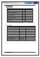
ES34169 Chassis User’s Manual Rev. A1 Packing List ES34169 Chassis Item Q’ty Chassis 1 3.5” HDD tray 4 2-port SAS / SATA-II backplane 2 70x15 mm rear fan 2 SATA-II cable, 440 mm 4 120 watts internal PSU 1 Screw pack for motherboard 1 Screw pack for HDD 1 USB 2.
ES34169 Chassis User’s Manual Rev. A1 Features z 120 watts internal power supply z Ideal for high storage capacity (Hot-swap HDDs) with RAID-5 functionality z Available for multi-media platform z 9.
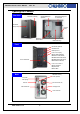
ES34169 Chassis User’s Manual Rev. A1 Opening the Chassis Overview Side Panel w/Venting Slim CD-ROM Carrier (Optional) Main Cable through hole w/ rubber pad Front Bezel (w/Key Lock) Intrusion switch USB & front Control cables Motherboard cage Front Card Reader (Optional) Slim ODD Cover USB 2.0 ports x2 Front Control Display: Power Status LED (Blue) HDD Access LED (Amber) LAN#1 Activities LED (Green) LAN#2 Activities LED (Green) Global Failure LED (Red) 4x 3.
ES34169 Chassis User’s Manual Rev.
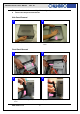
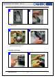
ES34169 Chassis User’s Manual Rev. A1 Motherboard Cage Removal 1 2 ■ Release 6 secure screws on the M/B cage ■ Remove the motherboard cage 3 4 ■ Detach the motherboard cage with System Cables (SATA, Power, Fan cables) through the cable routing hole ■ Disconnect the extension fan cables 5 ■ Finish detaching the M/B cage and make sure all the connection on backplane and PDB are still tight before assembly back the M/B cage www.chenbro.
ES34169 Chassis User’s Manual Rev. A1 Devices Installation Optional Parts: z Slim Optical Drive z 3.5” HDD z 4-in-1 Card Reader z Riser Card z 2.5” HDD Installing Slim Optical Drive (Slim ODD) Before install the slim ODD, the front bezel must be removed. The slim ODD carrier should be apart from the chassis. 1 2 ■ Assemble the adapter board with attached screws onto Slim ODD ■ Make sure the Slim ODD is fully seated with holder clip on the side.
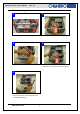
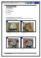
ES34169 Chassis User’s Manual Rev. A1 Installing 3.5” SATA-II Hard Drive 1 2 ■ Remove the HDD Carrier from the chassis and place the SATA-II HDD into it. ■ Attach the HDD screws on both sides 3 4 ■ Make sure the carrier is fully seated ■ Slide in the assembled HDD into the chassis, suggest install by the ID definition on the front panel (No need to remove the front bezel) Installing Card Reader 1 2 ■ Detach the front screw of Card Reader holder ■ Pull out the Card Reader holder www.chenbro.
ES34169 Chassis User’s Manual Rev. A1 3 4 ■ Remove the seal on the holder and make sure the sockets is right to the opening ■ Attach screws to fix the Card Reader 5 6 ■ Connect the short end of USB split cable to Card Reader ■ Install the assembled Card Reader back to the chassis with screw 7 ■ connect cable to USB port on M/B www.chenbro.
ES34169 Chassis User’s Manual Rev. A1 Installing Riser Card 1 2 ■ Remove the cap on slot holder ■ Detach the low profile slot bracket from rear window 3 4 ■ Assemble riser and low profile add-on card ■ Connect the cables before install. 5 6 ■ Install the riser card onto motherboard. (Please pay attention to the cable arrangement) ■ Attach screws on the rear side to secure the PCI card www.chenbro.
ES34169 Chassis User’s Manual Rev. A1 Installing 2.5” HDD 1 2 ■ Place 2.5” HDD underneath the Slim ODD ■ Fix the 2.5” HDD with attached screws Note: To install 2.5” HDD, disassemble the M/B cage is required. Connecting Devices z Four SATA-II cables for Hot-swap hard drive (HDD) z Power cables for M/B z Front panel I/O cables z USB 2.
ES34169 Chassis User’s Manual Rev. A1 Connecting Power Cables 1 2 ■ The DC harness comes with 20+4 pin as main connection for different M/B requirement. ■ Install and secure the DC harness cable to the M/B properly Connecting Front Panel I/O, LED and Slim ODD Cables a. USB 2.0 cable connection 1 ■ Front USB cable should be connected to on-board USB header properly depends on different M/B. www.chenbro.
ES34169 Chassis User’s Manual Rev. A1 b. Front display cable connection 1 2 ■ The cable with different connection for: Power on, HDD, LAN, FAIL and the front switch ■ Connect to the M/B according to the M/B pin header definition properly. c.
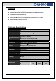
ES34169 Chassis User’s Manual Rev. A1 Power Supply Specification: Input Characteristics Output Characteristics Item Item Spec Spec Rated Input Voltage 115 V ~ 230 Vrms Output Voltage 3.
ES34169 Chassis User’s Manual Rev. A1 2-port SATA-II Backplane ES34169 is integrated with two SATA-II backplanes to support four 3.5” HDD with hot-swap feature. Hardware Specification: Part Number 80H104534-001 Rev. A1 Host Interface SATA 7-pin compatible HDD Interface SAS (22+7), SATA-II compatible Hot-Swap Yes, allows user to on line replace Hard Disk Drive Connectors 1. SATA-II x2 (to Host) 2. SAS (22+7) x2 (for HDD) 3.