
User Manual


7
4-Port SAS / SATA-II Backplane 80H102209 -010 ver. B0
User’s Manual
15Fl., No.150, Jian Yi Road, Chung Ho City, Taipei Hsien, Taiwan R.O.C.,
Tel: +886 2 82265500 Fa x: +886 2 82265392 Email: info@chenbro.com.tw
www.chenbro.com
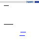
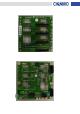
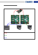
(1) [CN11 / CN21 / CN31 / CN41] : Connect to 22-pin SATA-II or 29-pin SAS HDD
(2) [LD11 / LD21 / LD31 / LD41] : Blue LED Indicate HDD Power
(3) [LD12 / LD22 / LD32 / LD42] : Green LED Indica te HDD Activi ty
Red LED Indicate HDD Failure
(4) [CN13 / CN23 / CN33 / CN43] : Connect to 7-pin SATA-II Host
(5) [CN1 /CN2] : 4-pin Power connectors
(6) [JF1 / JF2] : 3-pin Fan1 & Fan2 connectors
(7) [JP1] : Power Failure Input (From Redundant Power Supply)
(8) [JM1] : Power Failure Alarm Mute Output (to Redundant Power Supply)
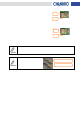
(9) [CN3] : HDD Activity LED Signal Input connector (from RAID Card)
Remove Jumper and connect the 5-pin to 4-pin HDD LED cable to the
CATHODE of the HDD activity connector on RAID card. Refer to your RAID
card’s user manual for the detailed pin definition
(10) [CN4] : HDD Fail LED Signal Input connector (from RAID Card)
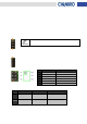
(11) [CN5] : Fan / Power / Temperature Fail LED output connector (to Front Panel LED Display)
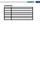
Pin Definition Function
1 LED(+) FAN/Power/Temp Fail LED
2 N/A
3 LED(-) Alarm Mute Switch
4
Buzzer Mute (+)
5 Key Pin
6 Buzzer Mute (-)
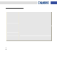
(12) [SW1] : Function Switch
SW1-1 SW1-2 SW1-3
ON
Fan1 Monitoring
Enable
Fan2 Monitoring
Enable
System Alarm Temperature
is 65°C
OFF
Fan1 Monitoring
Disable
Fan2 Monitoring
Disable
System Alarm Temperature
is 55°C
HDD1
HDD2
HDD3
HDD4
Pin 1
HDD1
HDD2
HDD3
HDD4
Pin 1
Key Pin
Key Pin