
User Manual


8
4-Port SAS / SATA-II Backplane 80H102209 -010 ver. B0
User’s Manual
15Fl., No.150, Jian Yi Road, Chung Ho City, Taipei Hsien, Taiwan R.O.C.,
Tel: +886 2 82265500 Fa x: +886 2 82265392 Email: info@chenbro.com.tw
www.chenbro.com
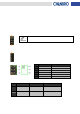
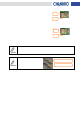
Power Supply Alarm Mute Connector Definition
Pin 1: Ground
Pin 2: Alarm mute signal output to PS U (Active low)
Power Supply Alarm Signal Connector Definition
Pin 1: Ground
Pin 2: PSU fail signal (TTL) input from PSU (Active low)
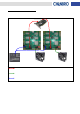
Only redundant PSU come with the failure alarm and alarm mute reset control via
signal connector. Make sure the redundant PSU that user applied come with the
connectors above.
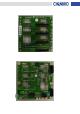
This picture shows the standard
“2510 2-pin” type PSU alarm signal
connectors which fitting Chenbr o
LED board.
Pin 1
Pin 2
Pin 1
Pin 2
Mute (Yellow & Black wire)
TTL (Red & Black wire)