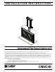
INSTALLATION INSTRUCTIONS Instrucciones de instalación Installationsanleitung Instruções de Instalação Istruzioni di installazione Installatie-instructies Instructions d´installation Automated Flat Panel Ceiling Lift This device complies with part 15 of the FCC rules. Operation is subject to the following 2 conditions: (1) This device may not cause harmful interference, and (2) this device must accept any interference received, including interference that may cause undesired operation.
CM2C40 Installation Instructions CSAV, Inc., and its affiliated corporations and subsidiaries (collectively, "CSAV"), intend to make this manual accurate and complete. However, CSAV makes no claim that the information contained herein covers all details, conditions or variations, nor does it provide for every possible contingency in connection with the installation or use of this product. The information contained in this document is subject to change without notice or obligation of any kind.
Installation Instructions CM2C40 CONTENTS INSTALLATION REQUIREMENTS .............................................................................................................. 5 Power Requirements and Wiring ............................................................................................................... 5 INSTALLATION ............................................................................................................................................
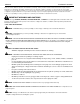
CM2C40 Installation Instructions LEGEND 4 Tighten Fastener Pencil Mark Apretar elemento de fijación Marcar con lápiz Befestigungsteil festziehen Stiftmarkierung Apertar fixador Marcar com lápis Serrare il fissaggio Segno a matita Bevestiging vastdraaien Potloodmerkteken Serrez les fixations Marquage au crayon Loosen Fastener Drill Hole Aflojar elemento de fijación Perforar Befestigungsteil lösen Bohrloch Desapertar fixador Fazer furo Allentare il fissaggio Praticare un foro Beves
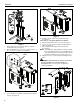
Installation Instructions CM2C40 INSTALLATION REQUIREMENTS 1. The CM2C40 has been designed to be mounted either hanging from an overhead structure or mounted to existing stud wall structures. 2. 3. Install interface bracket or mounting buttons to display following the instructions provided with bracket. Measure the distance from the center of a bottom mounting button to the lowest point of the display. Record measurement.
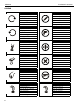
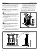
CM2C40 Installation Instructions 6 10 10 6 x2 9 Figure 5 5 4 Figure 3 7. 8. Remove two locknuts securing faceplate to faceplate mounting bracket. (See figure 4) Move faceplate up one set of holes to adjust location 1" or two sets of holes to adjust 2". (See figure 4) 1" (25MM) 10. Using the remote control, lower the lift until it stops. (See figure 3) If more than 2" of faceplate adjustment is required: 11. Raise lift following instructions in step 6. (See figure 3) 12.
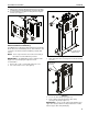
Installation Instructions CM2C40 15. Align studs in faceplate with appropriate holes in faceplate mounting bracket and hang faceplate on bracket with studs. 16. Secure faceplate to faceplate mounting bracket using two locknuts. (See figure 7) 1 x2 16 x2 Figure 7 Cable Installation and Routing The CM2C40 has an integrated cable management system that allows cables to be automatically "fed out" as the lift raises, and "reeled in" as the lift lowers while maintaining constant cable tension.
CM2C40 Installation Instructions 4 From Display x1 5 5 6 8 4 x3 8 4 x2 7 7 9 10 10 Figure 10 8 9
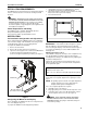
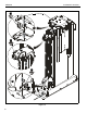
Installation Instructions CM2C40 6. Route cable(s) down through opening at rear of middle cable clamp mounting bracket. (See figure 10) and (See figure 11) NOTE: If plug on cable will not fit through opening loosen or remove one screw securing middle cable clamp mounting bracket to mount frame and pivot middle cable clamp mounting bracket to the side until plug can be routed behind bracket. 13.
CM2C40 Installation Instructions of travel must be considered when location the mount and a stop bar must be installed along the top edge of the opening in the ceiling. The stop bar must span the entire width of the front and back openings, and protrude outward into the opening a minimum of 1/2".
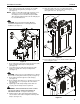
Installation Instructions CM2C40 7. While maintaining dimensions referenced in figure 15, mark base plate mounting hole locations. (See figure 16) 8. Drill pilot holes at marked locations. 9. Mark four side bracket mounting hole locations if applicable. (See figure 16) 10. Drill four pilot holes at marked locations. 11. Secure base plate to structure using either two (wall mount) or six (ceiling mount) 5/16" flat washers and two or six six 5/16" x 2 1/2" lag screws. (See figure 16) 12.
CM2C40 Installation Instructions NOTE: Holes are provided in the faceplate for use with a padlock or similar locking device, if desired. In addition, the pin and nut may be removed from the upper holes and moved to the lower holes for use as a more permanent locking device.
Installation Instructions CM2C40 2. Bottom Cover Installation After the CM2C40 has been properly configured for the display and the display installed, the bottom cover height must be adjusted to ensure proper fit into ceiling. 3. WARNING: IMPROPER INSTALLATION CAN LEAD TO SEVERE PERSONAL INJURY OR DAMAGE TO EQUIPMENT! Weight of bottom cover MUST NOT exceed 25lbs (11.34kg).
CM2C40 5. Installation Instructions Assemble bottom cover to cover mounting plate using #10-24 screws a minimum of 1/4" plus the thickness of the cover material long. (not provided). (See figure 25) There is an upward travel limit adjustment screw and a downward travel limit adjustment screw located on the top right hand side of the mount. (See figure 27) NOTE: 10 full turns of the "Extend" or "Retract" travel adjustment screws is equal to 1" of display travel. Cover Mounting Plate Bottom Cover 6. 7.
Installation Instructions CM2C40 Lift Column Bearing Adjustment The upper and lower lift columns are aligned using two lift bearings, one upper and one lower. Bearing adjustment is pre-set at the factory, however, there may be times when it is required to make slight adjustments in bearing tightness to eliminate excess play in lift columns or noise.
CM2C40 Installation Instructions Extended Programming Capabilities The CM2C40 allows for extended programming to make the mount compatible with other devices such as a Universal Remote or other control devices through a serial connection.
Installation Instructions CM2C40 NEC Protocol: Table 1-1: IR System Code The modulated carrier is usually derived from 455kHz and is 1/12 of the frequency with 1/3 duty cycle. Switch # 1 When data are transmitted repeatedly, the frame cycle is 107.9ms or 186 period. A frame consists of a syn pulse, an eight-bit custom code, an eight-bit inverted custom code, an eight-bit data code and an eight-bit inverted data code. The timing definitions of the output code waveform are shown below.
CM2C40 Installation Instructions IR-SE15 Programming IR-SE15 Control Features: • • • Carrier Frequency:38KHz Protocol:NEC - Full Repeat System Code(s):6E (Default) - Multiple Codes Selected via Key-Press (see below) Table 1-2: IR-SE15 Control Codes Key Number Key Name Hex Code 1 HOME 02 2 SAVE 1A 3 UP 07 4 LEFT 09 5 STOP 0A 6 RIGHT 0B 7 DOWN 0D 8 PRESET 1 12 10 PRESET 2 13 12 PRESET 3 14 To Change System Code: 1. Press and Release Key 3 + 7 (Enter Setup Mode) 2.
Installation Instructions CM2C40 IR-SC33a Programming IR-SC33a Control Features • Carrier Frequency: 38KHz • Protocol: NEC - Full Repeat • System Code: 6E Table 1-4: Key Number Key Name Hex Code 3 HOME 02 8 RETRACT 07 10 LEFT 09 12 RIGHT 0B 14 EXTEND 0D 19 PRESET 1 12 20 PRESET 2 13 21 PRESET 3 14 27 SAVE 1A 3 8 12 10 14 19 20 21 27 19
CM2C40 Installation Instructions Serial Communications NOTE: Check with the appropriate automation system vendor for available drivers and/or software for any external devices.
Installation Instructions CM2C40 Address Description: Multiple Chief devices can be used on the same network by setting each device to a different address. Note: All units ship with a default address of 0 Address Table: Addresses are set using dipswitches located next to power inlet on mount.
CM2C40 Installation Instructions CM2C40 Hardware Reference Motor Control Hardware Information (See figure 31) RS485 Network Programmable Paramaters and Status Bit Assignments RS485 Network Programmable Parameters Parameter Name Range Factory Default Units Identifier 0 Custom Code 1-32687 0 - 1 Maximum Movement Time 100-6000 3100 0.01 sec 2 Extend Speed 1-100 100 % 3 Retract Speed 1-100 100 % 4 Ramp UP Time 10-100 100 0.01 sec 5 Ramp DOWN Time 10-100 100 0.
Installation Instructions CM2C40 1st Position of switch array 1st Position of connector array 1st Position of connector array Figure 31 CM2C40 Connectors and Switches 23
CM2C40 Installation Instructions CM2C40 Interface Board Hardware Information (See figure 31) Dry Contact Closures The unit provides dry contact outputs for system feedback, or to control other devices. To complete circuits to external devices: 7. 8. 9. Connect the common wire from your switch to terminal 7. (See figure 32) Connect the 'up' wire from your switch to terminal 5. Connect the 'down' wire from your switch to terminal 6.
Installation Instructions CM2C40 Other Dry Contact Options Extend Retract with Single Switch Pins 1 and 2 on 9 pin Connector. (See figure 31) and (See figure 33) Figure 33 Voltage Sense External Power Source Unit extends and stays extended when voltage from an external source is applied across pins 3 and 4 on connector J1. When voltage is removed unit retracts.
CM2C40 Installation Instructions Retract Error Input NOTE: Units are shipped with error contacts "Normally Open". To set unit to respond to "Normally Closed" error contacts contact a Chief Technical Support representative by calling 1-800-582-6480, or by visiting www.chiefmfg.com. When unit receives a Retract error signal during a Retract operation, the unit will immediately stop and reverse direction.
Installation Instructions CM2C40 Connector and Switch Assignments All Dipswitches are in the "OFF" position when shipped from factory.
Figure 40 1.67 7.00 2X .63 2X .50 .406 DOOR BRACKET AND MOUNTING HOLES 4X CEILING MOUNTING HOLES 5.90 2X 3.04 23.75 21.75 19.25 19.00 20.50 19.00 4.00 10.21 11.02 2.50 1.31 30.74 +7.60 - .00 28.38 BOTTOM OF DOOR RANGE OF ADJUSTMENT +2.00 - 4.50 TOP MOUNTING BUTTON 11.60 2X .91 2X 4.25 APPROX. 40" OF TRAVEL 3.26 (2) SIDE MOUNTING BRACKETS (1 PER SIDE) 7.
Installation Instructions CM2C40 Troubleshooting SYMPTOM Lift does not respond POSSIBLE CAUSE • • • No Power to Mount 12V trigger option being used Overheated motor CORRECTIVE ACTION Verify Power to Mount Normal Operation See "Low Voltage Sensing" section Allow motor to cool for 10 to 15 minutes 29
CM2C40 Installation Instructions USA/International Europe Asia Pacific 8820-000030 2007 Chief Manufacturing www.chiefmfg.com 11/07 A P F A P F A 8401 Eagle Creek Parkway, Savage, MN 55378 800.582.6480 / 952.894.6280 877.894.6918 / 952.894.6918 Fellenoord 130 5611 ZB EINDHOVEN, The Netherlands +31 (0)40 2668620 +31 (0)40 2668615 Room 30I, Block D, Lily YinDu International Building LuoGang, BuJi Town, Shenzhen, CHINA.