
TV Mount User Manual


Installation Instructions JWP-V
11
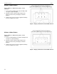
300mm x 200mm Pattern
For the 300mm x 200mm hole pattern, do the
following:
1. Select eight Phillips head M6 screws (110) from
Bag B and eight spacers (120) from Bag C.
2. Attach the interface bracket (20) using the hole-
pattern on the back of your display as shown in
Figure 7.
3. Tighten each screw. To prevent equipment damage,
do not over-tighten the screws.
400mm x 200mm Pattern
For the 400mm x 200mm hole pattern, do the
following:
1. Select six Phillips head M6 screws (90) from Bag B
and six spacers (120) from Bag C.
2. Attach the interface bracket (20) using the hole-
pattern on the back of your display as shown in
Figure 8.
3. Tighten each screw. To prevent equipment damage,
do not over-tighten the screws.
Figure 7. Display with 300mm x 200mm Hole Pattern
Figure 8. Display with 400mm x 200mm Hole Pattern