
TV Mount User Manual
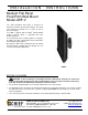


Installation Instructions JWP-V
9
Interface Bracket Installation
The following sections describe how to install the
interface bracket (20) for a specific hole-pattern on
your display.
This procedure provides a general guideline to follow
when installing the interface bracket after selecting the
mounting-hole pattern procedure that matches your
display. For example: To install the interface bracket
using the 200mm x 100mm mounting-hole pattern, use
the procedure on page 10.
WARNING: You must use proper attaching
hardware to install the interface bracket. Failure to
use proper attaching hardware may result in
equipment damage or serious personal injury.
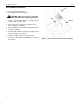
1. Lay the interface bracket (20) over the mounting
holes on the back of the display, making sure to
center the interface bracket as much as possible.
NOTE: A typical example of where to place the spacers
between the display and interface bracket is
shown in Figure 4.
2. In general, to install the interface bracket, do the
following:
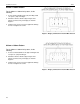
a. Select the appropriate mounting-hole pattern, as
described in the following sections, to attach
the interface bracket (20) to back of display.
b. Select the appropriate screws from Bag A or B
and spacers from Bag C to mount the interface
bracket to the back of the display.
c. Tighten each screw. To prevent equipment
damage, do not over-tighten the screws.
CAUTION: The screw and spacer length must
not exceed the depth of the mounting-hole. Using
improper hardware may result in equipment damage
or serious personal injury.
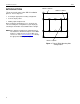
Figure 4. Attaching Interface Bracket to Display
SCREW*
(BAG A OR B)
MOUNTING
HOLE
DISPLAY
SPACER
(BAG C)
20