I N STA L L AT I ON I N S T R UC T I O N S In-Wall Accessory Boxes PAC525/526
PAC525/526 DISCLAIMER Milestone AV Technologies and its affiliated corporations and subsidiaries (collectively “Milestone”), intend to make this manual accurate and complete. However, Milestone makes no claim that the information contained herein covers all details, conditions or variations, nor does it provide for every possible contingency in connection with the installation or use of this product. The information contained in this document is subject to change without notice or obligation of any kind.
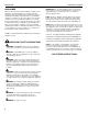
Installation Instructions PAC525/526 DIMENSIONS PAC525 14.25 362 10.93 277.6 3.00 76.2 1.13 28.6 1.72 [43.7] 1.36 [34.5] 2.57 65.2 1.38 34.9 .38 9.5 4.75 120.7 0.87 [21.8] 3.73 94.9 15.40 391.1 3.88 98.4 4.50 114.3 4.50 114.3 7.00 177.8 7.00 177.8 3.00 76.2 9.00 228.6 10.26 260.7 2.57 65.2 2.57 65.2 9X .75 X .25 ZIP TIE ANCHOR HOOKS P PAC526 1.36 [34.5] 1.72 [43.7] 0.87 [21.8] 14.25 362 11.75 298.5 5.00 127 1.13 28.6 2.57 65.2 1.82 46.2 .82 20.8 7.13 181 3.88 98.4 3.73 94.
Installation Instructions PAC525/526 LEGEND + Tighten Fastener Pencil Mark Apretar elemento de fijación Marcar con lápiz Befestigungsteil festziehen Stiftmarkierung Apertar fixador Marcar com lápis Serrare il fissaggio Segno a matita Bevestiging vastdraaien Potloodmerkteken Serrez les fixations Marquage au crayon Loosen Fastener Drill Hole Aflojar elemento de fijación Perforar Befestigungsteil lösen Bohrloch Desapertar fixador Fazer furo Allentare il fissaggio Praticare un foro B
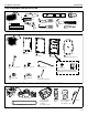
Installation Instructions PAC525/526 optional TOOLS REQUIRED FOR INSTALLATION 3/16” 1/4” Stud Sensor #2 Flathead 1 2 3 4 5 Punch #2 Phillips PARTS INCLUDED * Items may vary depending on specific model number. A Box Cover B Box Frame C D Install Box Template/Temporary Cover Grounding screw installed at factory E F 1/4 - 20 x 2 1/2” Screw (4x) #6 - 32 x 3/8” Screw (8x) G Security Hex Key #10 - 32 x 3/8” Earthing symbol IEC 60418 No.
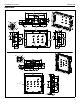
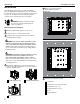
Installation Instructions PAC525/526 INSTALLATION 5 Plan box and component needs. The PAC525/526 is intended for use both in installations where an existing finished drywall wall is present, and where the wall surface has not been finished and the structural studs are exposed. The wall then must be finished around the opening of the box after the box has been installed.
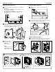
Installation Instructions PAC525/526 PAC525/526 Site Preparation PAC525/526 Box Preparation 11 Remove knock-outs in box as predetermined in 7 Using a level, draw a horizontal line at lower edge of step 5. install site. A - STUD ATTACHMENT - create exploratory hole to confirm edge of stud/studs. B - DRYWALL ATTACHMENT - mark horizontal cut locations ensuring a minimum 1/2” distance from each stud. A B B 12 Loosely attach components and conduit (cut to length) to box to ease fitting into wall opening.
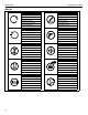
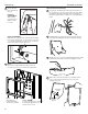
Installation Instructions PAC525/526 14 Secure box into PAC525/526 Final Finishing 16 Using preferred attachment method (zip ties, bands, etc. - place by methods chosen. none included), secure AV components and cables within the wall box. Attachment methods may use integrated attachment points at back of wall box or other appropriate points. DRYWALL ATTACHMENT: Slide locking cleats into place. Tighten screws to secure.
Installation Instructions PAC525/526
Installation Instructions PAC525/526
Installation Instructions PAC525/526
PAC525/526 Installation Instructions USA/International Europe Chief, a products division of Milestone AV Technologies 8800-002517 Rev01 2014 Milestone AV Technologies www.chiefmfg.com 09/14 Asia Pacific A P F A P F A 6436 City West Parkway, Eden Prairie, MN 55344 800.582.6480 / 952.225.6000 877.894.6918 / 952.894.6918 Franklinstraat 14, 6003 DK Weert, Netherlands +31 (0) 495 580 852 +31 (0) 495 580 845 Office No.