
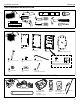
Installation instructions


7
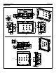
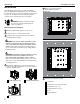
PAC525/526 Site Preparation
Using a level, draw a horizontal line at lower edge of
install site.
A - STUD ATTACHMENT - create exploratory hole to
confirm edge of stud/studs.
B - DRYWALL ATTACHMENT - mark horizontal cut
locations ensuring a minimum 1/2” distance from
each stud.
7
12
Align on lower edge drawn line (A) and horizontal
marking for inside stud location (B).Use enclosed
template or housing as a template, drawing line
around top and sides of housing.
8
A
A
A
B
B
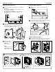
Cut along outside
edge of line using
utility knife.
Remove drywall.
NOTE:
Cutting past corners
weakens the cleats’
ability to hold securely.
9
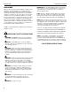
PAC525/526 Box Preparation
10
Once wall opening is completed, check stud depth. If 3.5” or greater, proceed to step 11. If less than 3.5” deep, modify depth
of box as follows before proceeding: CAUTION: Injury may occur on sharp edges. Carefully discard the removable tabs.
A - Remove box flange by removing screws.
B - Snap off removable tabs
at perforations provided.
C - Reinstall box flange. Reattach screws.
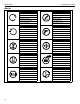
11
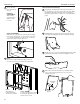
PAC525/526 Box Installation
Feed attached conduit through cut-out and insert box
into opening in wall. Tighten component connections.
13
B B
Installation Instructions
PAC525/526
Use four #6 screws (F)
and nuts (H) to assemble
the switch box from either
inside or outside the
PAC525 or PAC526.
Mark the
four corners.
CAUTION:
Avoid sharp edges.
Remove knock-outs in box as predetermined in
step 5.
Loosely attach components and conduit (cut to length)
to box to ease fitting into wall opening.