
User's Manual


Model: PAC-500 Installation Instructions
4
INSTALLATION AND ASSEMBLY
The following instructions are applicable to:
• Three 2x4 studs, 16" on center; other installations
are possible with increased framing complexity.
• MWR/PWR (single swing arm) and PNR (double
swing arm) mounts.
OPEN WALL
1. Determine approximate mounting location, keeping in
mind the display size.
! IMPORTANT: Installation of housing (10) in 2x4 wall
results in nearly direct contact with vertical studs and
opposite (back) wall. Inadequate space will remain for
electrical wires/cables, plumbing, ductwork, or insulation.
Locate housing (10) accordingly.
2. Use a stud sensor to locate applicable wood studs.
Mark locations with a pencil.
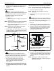
3. Center and level housing (10) between marked studs.
Using housing (10) as a template, draw pencil line
completely around housing (10) (See Figure 2).
NOTE: A 1/4" gap between sides of housing (10) and
adjacent studs is typical.
Figure 2: Open Wall
WARNING: ELECTRICAL SHOCK HAZARD! Cutting
or drilling into electrical wires and cables can cause
DEATH or SERIOUS PERSONAL INJURY! ALWAYS
make certain area behind mounting surfaces is free of
electrical wires and cables before cutting, drilling, or
installing mount fasteners.
WARNING: EXPLOSION AND FIRE HAZARD!
Cutting or drilling into gas plumbing can cause DEATH
or SERIOUS PERSONAL INJURY! ALWAYS make
certain area behind mounting surfaces is free of gas,
water, waste, or any other plumbing before cutting,
drilling, or installing mount fasteners.
4. Cut drywall on outside edge of line (to facilitate
installation of housing (10)) and remove.
FRAME HOUSING
The exposed portion of the center wood stud must be
removed and the resulting cavity completely framed with
wood. The following steps are suggested; the actual
procedure is dependent upon the specific installation.
WARNING: STRUCTURAL FAILURE HAZARD!
Ensure removal of center stud will not cause
unacceptable loss of structural strength. Consult a
qualified building contractor and applicable building
codes. Failure to take adequate precautions can
cause DEATH or SERIOUS PERSONAL INJURY!
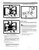
1. Remove exposed portion of center wood stud flush
with upper and lower drywall edges (See Figure 3).
NOTE: Stud may be attached to the opposite (back) wall.
Figure 3: Frame Housing
2. Cut 4 support blocks out of 2x4 wood, each
approximately 8" long.
3. Attach each support block to the corresponding stud
with three #10 x 2-1/2" countersunk wood screws.
Ensure that screws are far enough from end of block
to prevent interference with framing screws installed
in next step (See Figure 3).
NOTE: Use of wood screws (not included) instead of nails
is less likely to cause damage to surrounding
drywall or paint.
4. If necessary, cut rectangular hole in horizontal
framing to accomodate electrical box. Do NOT
eliminate bolts (100) to accomodate electrical
installation. All 12 bolts (100) must be used to secure
housing (10) to wall structure.
Wood Studs
Housing
1/4"
Horizontal
Framing
Support
Blocks
(4 places)
Top View
Wood
(5 places)
Screws
(Typical for each
support block)