
User's Manual


Installation Instructions Model: PAC-500
5
5. Attach horizontal framing to each support block with
two #10 x 2-1/2" countersunk wood screws (See
Figure 3).
INSTALL HOUSING
WARNING: ELECTRICAL SHOCK AND FIRE
HAZARD! Consult a qualified electrical contractor and
applicable electrical codes. Failure to take adequate
precautions can cause DEATH or SERIOUS
PERSONAL INJURY!
1. If applicable:
• Attach electrical box to housing (10) and connect
electrical wiring.
NOTE: The cutout in housing is sized to accommodate a
standard RACO Single Gang junction box.
• Route audio/visual cables through grommet (not
supplied) into housing (10).
NOTE: Housing (10) can be rotated 180° to position
electrical and audio/visual cutouts.
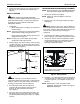
2. Center housing (10) in framed cavity. Ensure housing
(10) protrudes 3/8" - 1/2" beyond front face of wood
stud (for 1/2" drywall; adjust as required for other wall
construction) (See Figure 4).
Figure 4: Install Housing
CAUTION: Housing (10) must either be in direct
contact with studs/horizontal framing, or shims must be
installed. Failure to do so will result in deformation of
housing (10) when bolts (100) are tightened.
3. Cut and overlap shims (200) as required to
completely fill space between fastener holes in
housing (10) and studs/horizontal framing
(See Figure 4).
4. Using key (180) or bit (190) install all 12 bolts (100)
through housing (10) (and shims (200), if required)
into studs/horizontal framing (See Figure 4). Tighten
securely.
TRANSFER MWR/PWR/PNR MOUNT ASSEMBLY
NOTE: See instructions that came with MWR/PWR/PNR
mount for specific display removal procedures.
1. Disconnect all cables from display.
NOTE: Cables can remain installed in mount arm
channel(s).
2. Remove PAC-140 Q-Clamp (if installed) and open
latching flag.
WARNING: Display is very heavy! Ensure display can
be safely lifted and maneuvered as required to remove
from mount. Failure to take adequate precautions can
result in serious personal injury or damage to
equipment!
3. Lift and maneuver display mounting buttons out of
button openings. Place display on protective surface.
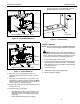
4. Using 9/16" wrench, remove and discard four bolts
and washers attaching top and bottom brackets to
mount assembly (See Figure 5). Place mount
assembly on protective surface.
Figure 5: Remove Mount
5. Using key (170), attach upper bracket (20) to housing
(10) with screws (70), washers (120), and washers
(110) (See Figure 6). Do not tighten screws (70) at
this time.
NOTE: Bracket (20) is shown centered for PNR
installation. Bracket (20) is offset to the right for
MWR/PWR installation.
200
3/8" - 1/2"
(12 places,
as required)
100
(12 places)
Wood
Stud
NOTE: PNR mount faceplace removed for clarity;
MWR/PWR mount similar.
Attach Bolts