
User's Manual


Installation Instructions Model: PAC-500
7
Figure 10: Install MWR/PWR Mount
Figure 11: Install PNR Mount
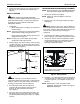
10. Using key (170), securely tighten screws (70)
attaching upper bracket (20) to housing (10) (See
Figure 6).
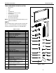
11. Using key (170), install screws (70), washers (120),
and washers (110) through lower bracket (30 [MWR/
PWR] or 40 [PNR]) into housing (10) (See Figure 10)
or (See Figure 11). Tighten securely.
12. Install covers (160) to unused threaded holes in back
wall of mount (10).
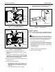
13. Finish housing (10) edge gaps:
• Moulding (50) and (60) may be installed. First
apply tape (150) to inner surface of long leg of
moulding, then press moulding into place (See
Figure 12).
• Other (optional) framing may be installed.
• Housing edge gaps may be filled with (optional)
drywall compound or other filler material.
Figure 12: Install Moulding
INSTALL DISPLAY
NOTE: See instructions that came with MWR/PWR/PNR
mount for specific display installation procedures.
WARNING: Display is very heavy! Ensure display can
be safely lifted and maneuvered as required to install to
mount. Failure to take adequate precautions can result
in serious personal injury or damage to equipment!
1. Ensure latching flag is fully opened.
2. Lift and maneuver display such that all buttons fit into
button openings on mount assembly. Lower display
firmly into place. Ensure each button has fully seated
in its button opening.
3. Close latching flag.
4. Install PAC-140 Q-Clamp (if applicable).
5. Attach all cables to display.
80
(2 places)
130 (2 places)
70
120
110
30
20
(2 places)
(2 places)
(2 places)
NOTE: Faceplace removed for clarity.
80
(2 places)
130 (2 places)
70
120
110
40
20
(2 places)
(2 places)
(2 places)
NOTE: Faceplace removed for clarity.
50
60
150
(18 places)
Edge of
drywall