Mirage S+/HD/WU, Matrix S+/HD/WU, Christie HD/DS+/DW, DLV USER MANUAL 020-100001-07
Mirage S+/HD/WU, Matrix S+/HD/WU, Christie HD/DS+/DW, DLV USER MANUAL 020-100001-07
NOTICE This equipment has been tested and found to comply with the limits for a Class A digital device, pursuant to Part 15 of the FCC Rules. These limits are designed to provide reasonable protection against harmful interference when the equipment is operated in a commercial environment. This equipment generates, uses, and can radiate radio frequency energy and, if not installed and used in accordance with the instruction manual, may cause harmful interference to radio communications.
Table of Contents 1 INTRODUCTION 1.1 1.2 1.3 Projector Overview ......................................................................................... 1-1 Components..................................................................................................... 1-3 Purchase Record and Servicing ....................................................................... 1-4 2 INSTALLATION & 2.1 2.2 2.3 2.4 2.5 2.6 Quick Setup ..........................................................................
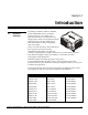
Section 1 Introduction 1.1 Projector Overview The Mirage S+/HD/WU, Matrix S+/HD/WU, Christie HD/DS/DW, DLV User Manual supports software v1.7d or higher. The projectors listed below are all professional 3chip projectors, based on next-generation Digital Light Processing (DLP) technology by Texas Instruments to deliver high quality, crisp, clean images.
Section 1: Introduction Main Features Native SXGA+, HD, HD2 or WUXGA resolution (model dependant) with all others fully scalable Internal scaling of stereo signals (Mirage models) 10-bit video processing Built-in multi-standard video decoder Display of NTSC, PAL and SECAM video input User replaceable Cermax Xenon lamp LiteLOC for constant brightness Intelligent Lens System (ILS) to save and restore lens settings Motorized lens mount for all models Auto-setup feature Inte
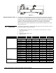
Figure 1.2 How the projector works The projector accepts data/graphics and video input signals for projection onto front or rear flat screens. High brightness light is generated by an internal Xenon lamp then modulated by three Digital Micro-mirror Device (DMD) panels that provide digitized red, green or blue color information.
Section 1: Introduction 1.3 Purchase Record and Warranty Registration Whether the projector is under warranty or the warranty has expired, Christie’s highly trained and extensive factory and dealer service network is always available to quickly diagnose and correct projector malfunctions. Service manuals and updates are available to service technicians for all projectors. If you encounter any problems with the projector and require assistance, contact your dealer or Christie Digital Systems.
Section 2 Installation & Setup 2.1 Quick Setup The instructions provided here are for those that are familiar with the projector and wish to quickly set it up and use it temporarily. Refer to the remaining subsections of this manual for a more complete setup. Step 1 Install a Projection Lens The projection lens is shipped separately from the projector and must be installed prior to setting up the projector. Install the projection lens as described in 4.5 Replacing the Projection Lens.
Section 2: Installation and Setup Step 4 Connect the Line Cord The North American-rated line cord is provided with each projector. Ensure that you are using a line cord, socket and power plug that meets the appropriate local rating standards. Plug the line cord to the AC receptacle located on the right hand side of the projector and the three-pronged end into a grounded AC outlet. Ensure the socket outlet is installed near the equipment and is easily accessible.
Section 2: Installation and Setup 2.2 Installation Considerations Proper installation of your projector will ensure the quality of your display. Whether you are installing a projector temporarily or permanently you should take the following into account to ensure your projector performs optimally. Installation type Choose the installation type that best suits your needs: front or rear screen, floor mount or inverted mount.
Section 2: Installation and Setup Rear screen installations There are two basic types of rear screens: diffused and optical. A diffused screen has a surface, which spreads the light striking it. Purely diffused screens have a gain of less than one. The main advantage of the diffused screen is its wide viewing angle, similar to that of a flat screen for front screen projection. This type of screen is suitable when a wide viewing angle is required but there is low ambient room lighting.
Section 2: Installation and Setup To fill a screen with an image, the aspect ratio of the screen should be equal to the aspect ratio of the image (expressed as the ratio of its width to its height). Standard video from a VCR has a 4:3 or 1.33:1 aspect ratio. For example, to display a VCR output with a 4:3 aspect ratio onto a 10-foot (3m) high screen, the width of the screen must be at least 13.3 feet (4m).
Section 2: Installation and Setup Vertical and horizontal position The correct vertical and horizontal position of the projector in relation to the screen depends on the lens type and the screen size. Ideally, the projector should be positioned perpendicular to the screen. This way, the image will appear rectangular instead of keystoned (trapezoidal).
Section 2: Installation and Setup Figure 2.1. Vertical Offset Examples Mirage S+/HD/WU, Matrix S+/HD/WU, Christie HD/DS+/DW, DLV User Manual 020-100001-07 Rev.
Section 2: Installation and Setup Figure 2.2. Lens Vertical Offsets 2-8 Mirage S+/HD/WU, Matrix S+/HD/WU, Christie HD/DS+/DW, DLV User Manual 020-100001-07 Rev.
Section 2: Installation and Setup The horizontal position of the image can be offset – that is moved to the left or right of lens center, by adjusting the fully motorized lens mount through software. The amount of horizontal offset available depends on the lens installed and if the image has already been vertically offset. Horizontal offset can also be expressed as the percent of half the image width – the number of pixels of shift to one side of lens center. Refer to Figure 2.
Section 2: Installation and Setup Figure 2.4. Lens Horizontal Offsets 2-10 Mirage S+/HD/WU, Matrix S+/HD/WU, Christie HD/DS+/DW, DLV User Manual 020-100001-07 Rev.
Section 2: Installation and Setup Mounting There are several methods for mounting the projector. Depending on your chosen installation, one method may be more suitable than another. In typical front and rear screen installations the projector can be mounted to a secure and level surface, such as a table or cart. Carts are useful when the projector has to be moved during a presentation or from site to site.
Section 2: Installation and Setup 2.3 Connecting Sources Sources connect to the Input Panel located at the back of the projector. See Figure 2.6. The upper right corner (INPUT 1) typically accepts an RGB signal from an external analog RGB source, or it can also be used for YPbPr signals or additional video sources. Just beside these BNCs, the DVI-I connector (INPUT 2) accepts digital or analog display signals from a computer.
Section 2: Installation and Setup Figure 2.7. Connecting RGB and Sync NOTES: 1) If for some reason the projector fails to recognize a signal as an RGB signal, specify this Color Space option within the Image Settings menu. See 3.5 Adjusting the Image. 2) To connect YPbPr signals–such as from DVDs or analog HDTV sources–to INPUT 1, use the red, green and blue BNCs as described in YPbPr Signals (below). YPbPr Signals Connect an YPbPr signal (component video) to INPUT 1 or INPUT 2 as shown in Figure 2.8.
Section 2: Installation and Setup Composite and S-Video INPUT 3 and INPUT 4 provide simultaneous connection of both a composite video source (INPUT 3) and an S-Video source (INPUT 4). See Figure 2.9. Figure 2.9.Connecting Composite or S-Video sources DVI Digital Video Use the DVI-I connector at INPUT 2 to connect either analog or digital video devices to the projector.
Section 2: Installation and Setup 2.4 Connecting Communications As an alternative to the projector’s keypad or remote, you may wish to communicate with the projector using a PC or other controller. Such a device sends commands and receives feedback via serial links (RS232 and RS422), Ethernet or GPIO communications to the projector, all described below. Remote Keypads As desired, direct the projector’s IR remote keypad towards the display screen or the projector’s IR sensors.
Section 2: Installation and Setup Figure 2.11. Connecting RS422 Ethernet Communications Ethernet Communications To add the projector to an existing Ethernet network with other equipment such as controllers and other projectors, connect standard CAT5 Ethernet cable between your Ethernet controller (or hub) and the Ethernet port on the side of the projector. Upon connection to an Ethernet network, the projector’s factory default IP address of 0.0.0.0.
Section 2: Installation and Setup Figure 2.12. RS232 Network MIXED NETWORK: To control multiple projectors with a computer/controller having an RS422 interface, first set them all to the same baud rate as your RS422 controller. NOTE: You must enable this combination of RS422 and RS232 in the Communications menu. Set the “Network Routing” option to “RS232 and RS422 Joined”. See Section 3 for details.
Section 2: Installation and Setup Figure 2.13. Ethernet Network SETTING THE PROJECTOR’S IP ADDRESS: Upon connection to most Ethernet networks, each projector’s factory default IP address of 0.0.0.0 triggers the network’s DHCP (Dynamic Host Configuration Protocol) server function to automatically assign an IP address that is valid and unique for use on that network.
Section 2: Installation and Setup Refer to Section 3.6 – Adjusting System Parameters and Advanced Control, System Configuration – Communication for additional information about ArtNet settings. ArtNet INTERFACE SETTINGS: Separating Networks By default, communications originating from one type of serial controller—RS232 vs. RS422 vs. Ethernet—stay on the corresponding network path. A “Separate” setting indicates this separation for “Network Routing” in the Communications menu.
Section 2: Installation and Setup 2.6 Power Connection The North American rated line cord is provided with each projector. Ensure that you are using a line cord, socket and power plug that meets the appropriate local rating standards. Plug the line cord to the AC receptacle located at the back of the projector, below the input panel, and the three-pronged end into a grounded AC outlet. Ensure the socket outlet is installed near the equipment and is easily accessible.
Section 3 Operation 3.1 About the Projector This section explains how to effectively operate the projector once it has been installed. It is recommended that you read this section and familiarize yourself with the components and the available menu options before you begin using your projector for the first time. Built-in Keypad The built-in keypad is located at the back of the projector, beside the input panel. Use it similarly to the IR remote to control the projector.
Section 3: Operation Lens Mount & Projection Lenses The projector is built with a motorized lens mount that allows for easy lens control and adjustment. This includes such functions as adjusting vertical and horizontal offsets, zoom and focus. The lens mount can be fitted with any one of the available optional lenses – see Section 6 - Specifications. Zoom and Focus – There are two internal lens motors that allow for quick motorized adjustment of zoom and focus.
Section 3: Operation 3.2 Laser radiation is emitted from the laser diode in the remote. Do not look directly into the beam of the remote.
Section 3: Operation Note: N/A on WU Models *These are toggle keys, which require you to press and hold or press twice or press and use the up/down arrow keys. NOTE: To turn the OSD off you must press OSD and . Figure 3.2. Remote Keypad 3-4 Mirage S+/HD/WU, Matrix S+/HD/WU, Christie HD/DS+/DW, DLV User Manual 020-100001-07 Rev.
Section 3: Operation Wired Remote You can convert the IR remote into a wired remote keypad using the cable provided with the projector. Connect one end into the remote and the other to the mini stereo connector on the input panel labeled as REMOTE. The wired remote is recommended when: The built-in keypad is inaccessible The lighting conditions are unsuitable for proper IR transmission NOTE: Leave the batteries in the wired remote for the laser key ( ) to work.
Section 3: Operation Table 3.1. Auto Setup What an “Auto Setup” Does OPTIMIZES: SETS TO DEFAULT: Pixel Tracking Contrast Pixel Phase Brightness Size and Blanking Auto Input Level (off) Vertical Stretch Detail (if video source) Position Filter Input Levels Luma Delay NOTE: You must have an unlocked channel present to use Auto Setup. Channel Channel Press to select a specific source setup (channel) defined and stored in projector memory.
Section 3: Operation Input 6 Input 6 Press Input 6 to display from the INPUT 6 interface module installed in the Option 2 slot. NOTE: If you have the optional Dual SD/HD-SDI Module installed and there are two inputs connected here, the second input (B) is considered INPUT 8.
Section 3: Operation OSD OSD (On-screen display) Press OSD to hide the projector’s menu system during use. To see the menus again, do one of the following: Press and hold OSD for two seconds Press and release OSD followed immediately by Press OSD OSD Invisible menus are fully functional, enabling “hidden” access to numbered features and image adjustments by entering the corresponding sequence of key presses on the keypad.
Section 3: Operation The “Projector” checkbox (read-only) shows whether or not the projector physically connected to a keypad is listening to commands from that keypad. A checkmark means that connected projector is listening; if there is no checkmark, you are communicating with a different projector. To control a specific projector with the keypad, press Proj and then enter the threedigit number assigned to the projector you want to use.
Section 3: Operation Lens NOTE: Use the Shift key (built-in keypad) with the general keys to get the same effect as if using the arrow keys related to “Lens V” or “Lens H” on the IR remote. Laser to activate the laser pointer on the Press remote. This feature is useful when making presentations - just point the remote at the screen to highlight an area of your presentation. The closer you are to the screen the brighter the laser beam appears.
Section 3: Operation On-line Help If at any time you are uncertain what to do next, press Help to display summary information about the current menu or highlighted option. Press Help again to exit. In addition, a line of “hint” text is included at the bottom of some menus. 1. 2. 3. 4. 5. 6. 7. 8.
Section 3: Operation Once selected, change the setting as desired (see below) and press return to the current function menu. to save and Slide bars in menus – The current value for a given parameter, such as size or vertical stretch, appears to the left of its slide bar icon (adjustment window). This number often expresses a percentage, or it may have units associated with it (such as pixels, degrees Kelvin, etc.), depending on the specific option.
Section 3: Operation 1. 2. 3. 4. 5. 6. 7. 8. 9. 0. Communications 115200 Baud Rate for RS232 Baud Rate for RS422 115200 Projector 004 Network Routing All Joined Ethernet Settings Broadcast Key Backlight On Front IR Back IR On Wired Keypad Off 1. 2. 3. 4. Separate RS232 and RS422 Joined RS232 and Ethernet Joined All Joined Example of Pull-Down List If you prefer to quickly scroll through a list without first pulling it down, highlight the option and use . Press or when the desired choice appears.
Section 3: Operation NOTE: Press Exit at any time to cancel changes and return to the previously defined text. Editing Numerical Values Enter numbers directly from the keypad in order to specify numbers representing projectors, channels (source setups), or slots. As each digit is entered, it is displayed and the cursor moves on.
Section 3: Operation you choose for a VCR source may be very different from those you choose for a highresolution computer source, or one signal may simply vary from another signal used previously through the same input location. Once you have adjusted a display parameter, such as pixel tracking or contrast, all current settings are collectively stored in the projector's memory as a unique two-digit channel, such as 0 9 .
Section 3: Operation NOTES: 1) The current channel is highlighted upon entering the channel list, or, if this channel is not displayed here, the first channel in the list is highlighted. 2) Channels created automatically do not appear in the channel list unless a parameter for the channel has been changed.
Section 3: Operation Table 3.2. Abbreviations for Signal Type Abbrev. 4WH 4WV SG 5W 5WR SVid CVid Dig Signal Type Composite (4 wire) on HC input Composite (4 wire) on V input Sync-on-green Separate H,V Separate H,V swapped S-Video Composite Video Digital FUNCTIONS WITHIN THE CHANNEL SETUP MENU —To copy, delete or edit a channel, highlight the desired channel in the Channel Setup menu and do one of two things: Press Func if you want to copy the selected channel or delete this or other channels.
Section 3: Operation Figure 3.5. Deleting a Channel highlight any channel in the Channel Setup menu and press Func to go to the Channel Copy/Delete submenu. Select “Delete Unlocked to delete all unlocked channels. Select “Delete All Channels” to Only” and press delete all channels, even those that are locked. In either case, the current channel will remain but will be redefined from projector defaults.
Section 3: Operation NOTES: 1) If you enter a channel number that already exists; a dialog message appears indicating that this number is already in use–assign a different channel number. 2) You can define up to 50 channels. INPUT: 1-8, corresponding to where on the projector’s input panel the source is connected. If checked (default, except for automatically defined channels with unchanged parameters), this defined channel will then appear in the list available key is pressed.
Section 3: Operation Before You Begin Use Auto Setup ( Auto ) For a good and efficient first step in perfecting the image, press Auto . This initiates an automated process in which the projector quickly optimizes critical display parameters such as size, position, pixel tracking, etc., based on the type of incoming source data detected. An Auto Setup can save considerable setup time, and you can still modify the adjustments as desired using menu options described below.
Section 3: Operation Select “NO RESIZING” to display the image in its native resolution, which may or may not match the projector’s resolution. For example, for a source with a native resolution of 800 x 600, “No Resizing” in an SXGA+ projector will use the central 800 x 600 pixels and have a black border—the black border areas are unused areas. See below. Select “FULL SIZE” to use all pixels for displaying the image, regardless of source or original aspect ratio.
Section 3: Operation fill the screen from side-to-side and be centered between black bars at top and bottom. Size “Size” controls both the image width and height in tandem, maintaining the current aspect ratio (proportion) of the displayed signal data. Vertical Stretch “Vertical Stretch” adjusts the height of the image while keeping the width constant. Use “Vertical Stretch” to change the aspect ratio of the display.
Section 3: Operation H-Position This option moves the image right or left within the area of available pixels. NOTE: The value shown represents where the approximate center of the image lies in relation to the total number of pixels available horizontally. This varies widely according to the signal—watches the image while adjusting. V-Position This option moves the image up or down within the area of available pixels.
Section 3: Operation PIP Advanced Size & Position 1. 2. 3. 4. 5. Active Input Window Top Blank Bottom Blank Left Blank Right Blank Plug & Display 1600x1200 0 0 0 0 Native Resolution 60Hz PIP Advanced Size & Position 1. 2. 3. 4. 5. Active Input Window Top Blank Bottom Blank Left Blank Right Blank Plug & Display 1600x1200 49 2 485 67 Native Resolution 60Hz Figure 3.6.
Section 3: Operation Brightness (SHORT CUT: Press Bright and adjust the slide bar.) “Brightness” increases or decreases the amount of black in the image (0-100). For best results, keep close to 50. Start with a high value and decrease so that dark areas do not become black (i.e., are “crushed”). Conversely, high brightness changes black to dark gray, causing washed-out images. Gamma (SHORT CUT: Press Gamma and adjust the slide bar.
Section 3: Operation Noise Reduction “Noise Reduction” is similar to the “Filter” control, but operates in the post-sampling digital domain with a more subtle effect. Higher settings are most useful for clearing up noisy RGB images such as those from a PC. Adjust as desired, keeping in mind that reducing noise (which reduces high frequencies) may also soften the image. Color Space “Color Space” determines how the color components of an analog input signal are decoded for accurate color in the display.
Section 3: Operation VIDEO STANDARD: For all but the more unusual video standards available in the world, the projector automatically detects the incoming horizontal and vertical frequencies and sets the projector’s processing of this signal to the corresponding standard. The current video standard name appears in the Video Options submenu, and includes an “A” if it has been auto-detected.
Section 3: Operation TINT: This slide bar adjusts the red/green color hue for true color reproduction of video and HDTV signals connected to Input 3 or 4. For best results, adjust tint while displaying an external test pattern—otherwise, it is recommended that tint remain at its default setting. This control affects any incoming composite or S-video signal, delaying the luma signal (intensity) in relation to the chroma (color).
Section 3: Operation Temporarily enter a checkmark only if you are an experienced user and you have an unusual source that you feel needs further color temperature and/or input level adjustment. This compensates for incoming out-of-range drives (white) and black levels (black) that would cause “crushing” of light and dark colors in the image. After entering a checkmark, wait for the six slide bar values to stabilize, and then delete the checkmark and exit.
Section 3: Operation NOTES: 1) Input levels apply for the current source only, but for any color temperature used. 2) Assuming that color temperature has been set up based on the internal test patterns, you can then set up input levels for a given source so that it matches the color temperature of the internal test patterns. The Peak Detector is a tool to assist with defining individual input levels, enabling you to accurately set the Input Levels for any particular source with the appropriate image.
Section 3: Operation Figure 3.7. Adjusting Input Levels Using the Peak Detector (RED EXAMPLE SHOWN) Advanced Image Settings — SUBMENU Use the Advanced Image Settings submenu to make the adjustments necessary for lesser-used but more specialized applications on your projector. NOTE: 3D Source option is only available for Mirage HD. Advanced Image Settings Gamma Table 1. 2. Select Color Adjustment Color Temperature 3. Optical Aperture 4. Reserved 5. Simulation 3D 6. Motion Filter 7. 8.
Section 3: Operation NOTES: 1) If no user curves have been defined and downloaded to projector memory, only the 2.2 default gamma curve is available here – adjust as desired using gamma in the main Image Settings menu. 2) Some graphic material will look best with the video setting while some video material is best with the graphic setting. SELECT COLOR ADJUSTMENT: In “Select Color Adjustment”, choose an overall color palette for all images.
Section 3: Operation OPTICAL APERTURE - The optical aperture inside the projector controls the diameter of the light beam passing through the system. With a fully open aperture (slide bar default of “0”), the maximum amount of light passes through for maximum brightness in your images. Increase the slide bar setting to reduce the aperture diameter and maximize contrast ratio instead. Performance of aperture depends on the lens in use. NOTE: Optical Aperture also appears in the lamp menu.
Section 3: Operation FRAME DELAY — Set the number of lines delayed between the input signal and its appearance on screen, keeping in mind that projector processing always adds one frame of delay to the frame delay setting. For applications such as simulation, where the feeling of “real time” image response is a priority, a minimum setting is usually preferable.
Section 3: Operation 3D STEREO SYNC DELAY — Set when the L/R frames begin, defining the best reference point for synchronizing the display with your glasses. Proper adjustment of this delay should eliminate cross talk and odd colors caused by timing differences between the glasses and the projected display. Use this slide bar only if the Mirage 3D Stereo Sync Cable is connected between the projector’s GPIO port and a server. Slide bar values indicate the number of lines that are delayed.
Section 3: Operation Adjust Dark Interval to artificially increase the amount of dark time between displayed frames for stereographic 3D images. Higher settings provide more time for shutters in 3D glasses to open/close, ensuring that each eye sees the full display intended for it. Symptoms of cross talk and/or color artifacts can indicate need for adjustment. The Dark Interval range of adjustment depends on the vertical frequency of your source—the higher the frequency, the smaller the range.
Section 3: Operation 3D STEREO SYNC DELAY — This value is set when the L/R frames begin and by default, is automatically calculated based on signal timing; it defines the best reference point for synchronizing the display with your glasses. Proper adjustment of this delay should eliminate cross talk and odd colors caused by timing differences between the glasses and the projected display. Slide bar values indicate the number of lines that are delayed.
Section 3: Operation ACCUFRAME – Increasing the AccuFrame value will reduce the artifacts related to fast motion in simulation content. Symptoms of blurry objects or loss of apparent detail may indicate a need for this value to be adjusted. NOTE: If increasing AccuFrame does not improve image quality, reduce the value to 0. Increasing AccuFrame may increase ‘flicker’ of the display and may reduce overall brightness.
Section 3: Operation 3D SOURCE — When using a Mirage projector with HD or WUXGA resolution, a checkbox option called 3D Source will be added to the bottom of the Advanced Image Settings menu. This checkbox must be set by the user for all new 3D sources, and cleared for all new non-3D sources (default setting is checked). Once set, this value will be maintained for that source for all future uses. This option is also available under the Simulation 3D menu in Mirage HD projectors only.
Section 3: Operation Menu Preferences — SUBMENU Adjust the appearance, content and/or location of on-screen menus and messages. Enter a checkmark to enlarge menus and their text. You may have to adjust “Menu Location” to accommodate the increased menu area. LARGE MENU FONT — MENU LOCATION — Use the pull-down list to choose a pre-defined default or customized location for the display of all on-screen menus. To create a custom menu location quickly, choose a preset that is closest to the desired location.
Section 3: Operation SPLASH SCREEN SETUP —Use the Splash Screen to choose when you would like to display a special introductory splash screen image, such as your company logo, graphic or message. Always Off = A splash screen never appears Always On = A splash screen is always on behind the current display image, similar to wallpaper. Start-up Only – The splash screen logo appears at projector start-up only.
Section 3: Operation Network Routing NOTE: Not applicable for stand-alone projectors or simple serial networks with only one type of controller and linking. 1. 2. 3. 4. Separate RS232 and RS422 Joined RS232 and Ethernet Joined All Joined SEPARATE: Select “Separate” (factory default) to keep RS232, RS422 and Ethernet messages on their respective paths instead of being broadcast to the other types of ports. In Figure 3.8A, RS422 controls only the projector to which it is connected. In Figure 3.
Section 3: Operation IP ADDRESS: Enter a valid and unique IP address for use on the network to which the projector is currently connected. This address will overwrite any previous IP address such as the projector’s factory-defined default (0.0.0.0), or one that has been assigned by a DHCP server or other user. It takes approximately 10 seconds for the projector to respond at its new address.
Section 3: Operation ArtNet BASE CHANNEL: When advanced mode is enabled, the projector listens to data on 64 consecutive channels, or 10 consecutive channels when advanced mode is not enabled. The projector processes requests that come on either 10 or 64 consecutive channels beginning with the ‘base channel’ defined here.
Section 3: Operation Backlight Toggle to turn the built-in keypad backlighting on and off. Front IR / Back IR As needed for your application, set to “any” so that the front and/or rear IR sensor locations on the projector respond to the IR keypad. Set to “off” to disable. To disable both IR sensors, you cannot use the IR remote keypad to select the second OFF setting. This safeguard prevents accidentally disabling an IR keypad while you are using it.
Section 3: Operation Brightness Uniformity — SUBMENU Brightness Uniformity provides further refinement of displays already matched for their primary colors and overall light output. Use Brightness Uniformity to create an exceptionally smooth image in which no area appears brighter and/or more red, green or blue than another.
Section 3: Operation DEFINING “USER” COLOR GAMUTS: In some cases, you may find that none of the predefined “Select Color Adjustment” options exactly suit your needs. For example, you may require a unique color gamut (range) for a single projector or application, or you may need to precisely match colors across multiple adjacent displays.
Section 3: Operation Figure 3.11. CIE 1931 Chromaticity Diagram (without Yellow Notch Filter) NOTE: Keep new x,y coordinates within the original color gamut triangle shown here. PROCEDURE FOR X,Y ADJUSTMENTS: See 3.10, Using Multiple Projectors. COLOR SATURATION: Use this submenu if you do not have specific color coordinates in mind and will simply judge color performance by eye or meter.
Section 3: Operation Black Level Blending — SUBMENU Black Level Blending is a feature that eliminates the differences between black levels when edge blending multiple projectors. The Black Level Blending submenu provides many controls to allow the edges of adjacent images to be smoothly overlapped creating a “seamless” image.
Section 3: Operation NOTES: 1) See System Configuration – Diagnostics/Calibration, ILS Calibration for further details about calibration. 2) ILS control is a preference setting and will be retained between power cycles. System Configuration Test Pattern DIAGNOSTICS / CALIBRATION Choose the desired internal test pattern to display, or select OFF to turn off a test pattern. Alternatively, use the Test key for cycling through test patterns.
Section 3: Operation 8. Repeat Steps 3-7 for all remaining colors. Your RGB source should now be OK. Two sets of values are automatically saved with these controls—one value for Input #1, and one for Input #2 (analog). The current set of values depends on which source is in use. This enables a source to be processed correctly via two different inputs. Odd Pixel Adjustment 1. Red Odd Pixel Offset 2. Red Odd Pixel Gain 3. Green Odd Pixel Offset 4. Green Odd Pixel Gain 5. Blue Odd Pixel Offset 6.
Section 3: Operation Level Value Level Value defines the value to be used by the Level Detector in recognizing blacks and whites. See Level Detector, above. Aspect Ratio Overlay Selecting this option with a checkmark will overlay a number of common aspect ratio boxes on top of the source image. This is very helpful during the setup of the projector and can be turned off after desired specifications have been achieved. LiteLOC™ Calibration NOTES: 1) LiteLOC™ Calibration takes up to two minutes.
Section 3: Operation System Configuration The two “Option Card” Option Card 1: Dual SD/HD-SDI Module entries In the 1. Loop Thru Output Selection Input A to C, Input B to D Configuration menu 2. Configure Channels Automatic identify which optional input modules (a.k.a. cards) are present at 1. Input A to C, Input B to D 2. Input A to D, Input B to C INPUT 5 (Option 1) and 3. Main to C, PIP to D INPUT 6 (Option 2). If 4.
Section 3: Operation Signal Type #1 #2 #3 * Description (Input Location) 5 BNCs (RGBHV or YPbPr) DVI - I (analog or digital) Decoded signals (Input 3, Input 4, Composite video, S-Video, or any video signal via Input 1 BNC connectors or via an analog option card). #4 Analog Option Cards #5 Digital Option Cards #6 Digital Option Cards HD interlaced sources are not recommended for the PIP window.
Section 3: Operation PIP Size and Position – SUBMENU Most controls in the PIP Size and Position menu adjust the PIP (secondary) image in the same fashion as their counterparts in the main Size and Position menu adjust the main image—see 3.6, Adjusting the Image for details. Exceptions are: POSITION PRESETS –Set the location of the PIP (secondary) image in the display. ASPECT RATIO PRESETS – Choose the desired aspect ratio for your PIP pixels.
Section 3: Operation Image Optimization Use this setting to choose what is more important, image quality or switching between sources. Selecting Best Image Quality will ensure your image is always proper however when switching sources, the screen will go blank increasing your switching time. Smooth Switching allows for a cleaner transition between sources. The image will fade from one image to another according to the Fade Time control.
Section 3: Operation LAMP S/N (read-only) is the serial number recorded for the current lamp. When you install a new lamp and enter its serial number, the number will appear here. Enter a checkmark for LAMP MESSAGE to enable a warning message that will appear upon power-up when the lamp has reached the specified lamp limit and should be replaced.
Section 3: Operation POWER - This slide bar and number indicates how many watts are applied to the lamp. You can apply anywhere from approximately 60-65% of the maximum power intended for the installed lamp up to 100% of the lamp rating. Set for the number of watts as desired, keeping in mind that lower power levels produce dimmer images. When in either Power or Max Brightness modes, the power level remains constant. Specifying a maximum power level here is the same as operating in Max Brightness mode.
Section 3: Operation This option is also available under the Advanced Image Settings menu. See 4.6 – Adjusting the Image for details. OPTICAL APERTURE - This read-only option lists the lamps most recently installed and recorded in the projector. Lamp History automatically updates whenever you record a new lamp serial number—the new lamp is added to the bottom of the list.
Section 3: Operation How Old is My Lamp? When a new lamp is installed and its serial number recorded by selecting “Change Lamp” in the Lamp menu, the lamp timer resets to “0” and begins logging time for the new lamp. This tally appears in both the Lamp menu (see right) and the Status menu. 1. 2. 3. 4. 5. 6. 7. 8. To review the number of hours logged for previous lamps, consult the Lamp History menu.
Section 3: Operation Preliminary Calibration As a final part of the manufacturing process, all primary colors in the projector are precisely set to pre-established values to ensure that overall color performance is optimized and is as accurate as possible. Upon installation at a site, however, lighting and other environmental factors may slightly change how these colors appear on your screen.
Section 3: Operation 4. Display the Color Adjustments by X,Y menus for all projectors. Each menu shows the x/y coordinates defining the “Max Drives” color gamut for this projector. Note the values shown in one (any) of the displays. See Figure 3.14. Or use the “Copy From” function to copy them into a “User” gamut in one projector. Figure 3.14. Jot Down a Set of ”Max Drives” X/Y Values 5. In each projector, select a “User” color adjustment (1-4) to enable Color Adjustments by X,Y changes.
Section 3: Operation To match reds, decrease “Red X” until full field red screens match. To match greens, decrease “Green Y” until full field green screens match. To match blues, increase both “Blue X” and “Blue Y” until full field blue screens match. NOTE: For speed, enable the “Auto Color Enable” checkbox. Each color coordinate you select will then automatically trigger a full field display of the corresponding color.
Section 3: Operation Achieving Brightness WHAT IS BRIGHTNESS UNIFORMITY? When used to refine screens already matched for Uniformity their primary colors (see Matching Colors in Multiple Screens, above) and overall light output, proper adjustment of Brightness Uniformity can create an exceptionally smooth screen in which: No area of the screen appears more red, green or blue than another No area of the screen appears brighter than another Color and light output from one screen closely matches adjace
Section 3: Operation Step 1: General Setup 1a) Adjust primary colors (see Matching Colors in Multiple Screens) to ensure matched overall color temperatures and light output between screens. IMPORTANT Double-check that all WHITES and LIGHT OUTPUT are well-matched. 1b) Enable the Brightness Uniformity checkbox. This will enable access to the uniformity controls and will apply the settings to your image. 1c) Select the 13-Point test pattern for display.
Section 3: Operation Ensure that overall light output remains well matched from one screen center to the next. Where necessary, increase or decrease Lamp Power slightly to recover center matches. Step 2: Adjust Color (level of red/green/blue) in Eight Zones NOTES: 1) At this point, ignore the brightness of individual zones. 2) Always ignore menu colors. 2a) On each screen, compare the color temperatures in the eight target zones (four edges and four corners) to that of the color temperature of the center.
Section 3: Operation Adjust corner White Uniformity last—each corner adjustment affects only this quadrant. Repeat for each screen. Figure 3.18. Match Zones to Center Light Output Step 4: Readjust Color Temperature (level of red/green/blue) in Eight Zones 4a) Return to Steps 2a & 2b and, if necessary, fine-tune the zones so that they all still exhibit a single color temperature.
Section 3: Operation Figure 3.19. Edge Blending Concept For best results, use the same projector model and type throughout your display wall. In addition, avoid high-gain screens whenever possible—the optical performance of such screens demands minimal image offset, thus projectors must be located very close to one another. Edge blending software controls are located in the two-page Edge Blending submenu—access via Configuration menu, then go to the Geometry and Color menu and select Edge Blending.
Section 3: Operation Blend Midpoint determines the white level at the blend midpoint (the point equidistant between the beginning and end of the blend). Increasing the Blend Midpoint setting creates a blend that appears brighter than the rest of the image. Decreasing the Blend Midpoint setting creates a blend that is darker than the rest of the image. A setting of 50 means the midpoint is approximately 50% black—for best results in most applications, keep fairly close to this default. Figure 3.21.
Section 3: Operation Figure 3.22. Set Starting Points for Each Projector 4. SET BLEND WIDTH: On one projector, increase the Blend Width for an overlapping edge (for example, if the projector’s image is on left, its right edge overlaps the adjacent image—adjust Right Blend Width). Use the same setting on the second projector for this shared edge. 5. Re-adjust width (both projectors) until the overly bright band at the midpoint of the overlapping blends disappears or just changes to very light gray.
Section 3: Operation Adjustments can now be made to black level controls. To restore the use of Christie TWIST: 1. Disable black blending. 2. Power cycle the projector. 3. Begin using the TWIST controls. Black Level Blending Procedure NOTES: 1) Adjust white levels before adjusting black levels. 2) The zones in BLB menu correspond to the Edge Blend zones. If a given Edge Blend zone width is set to 0 (i.e. no blend on that side) then the corresponding BLB zone is disabled.
Section 3: Operation 6. The brightness and black hues of the blended region can be adjusted in more detail in case fine-tuning is needed (may be only necessary for blending a 2 x 2 projector display because of blending differs for the sides and center). NOTES: 1) The menu options vary depending on the Edge Blending parameters. 2) You may need to re-adjust the black level hues following the overlap adjustments on each blended edge.
Section 3: Operation 3.12 Error Conditions Occasionally the projector will encounter an error condition that can interrupt normal operation. Such a condition can be caused by a simple invalid keypad entry, an input signal error (most common) or a system error. The manner in which users are to be notified of error conditions is set in the Menu Preferences menu: To see error messages displayed on-screen, select the “Screen” or “All” option.
Section 3: Operation Other Signal Error Messages In addition to the common "Bad Sync" and “No Signal” errors, you may encounter a signal error message indicating that HSYNC and/or VSYNC are either too fast or too slow. When such a message appears, check the frequencies shown in the Status menu. If they are correct, the projector does not recognize the signal. On some PCs you may be able to change the settings to generate a compatible signal.
Section 3: Operation Table 3.5 Error Codes Code Description GENERAL 12 Software bug. Contact dealer/factory. 13 CRC error in flash ROM. Download new software. 14 Engineering-only programming is complete. Call Christie, replace TIPM. 15 Attempting to download code without being in boot mode 16 Invalid interrupt. Power off/on. If it persists, contact dealer/factory. 17 User forced system to stay in boot mode 18 Jumper for programming boot not installed 1E External 3D Input Sync missing.
Section 4 Maintenance 4.1 Warnings and Safety Guidelines The projector is an international regulatory agency approved product designed for safe and reliable operation. To assure complete safety at all times it is important to acknowledge the following precautions while operating the projector. WARNING Always power down the projector using appropriate procedure and disconnect all power sources before cleaning or servicing. WARNING Always remove the lens when shipping the projector.
Section 4: Maintenance Projector Location Operate the projector in an environment, which meets the operating range specified in Section 6 – Specifications. Do not operate the projector close to water, such as near a swimming pool. Do not operate in extremely humid environments. Do not place the projector on an unstable cart, stand or table. A projector and cart combination should be used with care.
Section 4: Maintenance Do not set or rest items on the power cord. Place the projector in an area where the projector cord cannot be abused or damaged by persons walking on it or by objects rolling over it. Operate the projector at the specified voltage only. Do not overload power outlets and extension cords as this can result in fire or shock hazards. The projector is equipped with a three-wire plug having a third grounding pin.
Section 4: Maintenance 4.2 Cleaning and Maintenance Guide Table 4.1. Maintenance Guide Part Description Lens Frequency Action As required Clean the lens only when absolutely necessary. A small amount of dust on the lens has very little effect on picture quality. To clean: Use a soft lint-free cloth without any chemicals. Use only a high-quality coated optics cleaning fluid, which can be purchased from most camera supply stores.
Section 4: Maintenance 4.3 Replacing Remote Batteries The IR Remote Keypad uses two AA size, 1.5V batteries (preferably alkaline). To install new batteries: 1) Open the battery compartment at the backside of the keypad by placing your thumb in the oval depression and sliding the cover out about ½ inch. See Figure 4.1. Remove the old batteries and properly discard. Wait a minute or two. 2) Place the new batteries in the compartment, orienting the Figure 4.1.
Section 4: Maintenance Table 4.2.
Section 4: Maintenance 1. TURN THE LAMP OFF (power) to turn the lamp off. Allow the cooling fans to stop Press automatically (within approximately five minutes) before proceeding with Step 2. This wait period is also required to allow the lamp to sufficiently cool before handling. 2. UNPLUG THE PROJECTOR When the cooling fans have stopped, turn the projector’s main switch off, and unplug. WARNING Always power down and unplug the projector prior to servicing. Allow the lamps to cool before handling 3.
Section 4: Maintenance Figure 4.3. Release the Lamp Lock 5. REMOVE THE LAMP MODULE Firmly grasp the lamp by its housing only and pull it straight out (lamp slides along guides) until it is free. See Figure 4.4. Discard the lamp using safe disposal/recycling practices. Figure 4.4. Remove Lamp Module 6. INSERT THE NEW LAMP MODULE Align the new lamp with the top and bottom guides on the left side of the lamp compartment (see Figure 4.5).
Section 4: Maintenance Figure 4.5. Insert New Lamp Module WARNING Improper installation could cause a serious meltdown inside the projector. 7. LOCK IN THE NEW LAMP MODULE Pull out and turn the lamp lock lever (turned up in Step 4) ¼ turn clockwise to “lock” the lamp in place. NOTE: If you can’t turn the lamp lock into position, it is likely the lamp is not fully inserted. In this case, partially remove the lamp and try pushing it back in again. Then, try switching the lock lever to the “lock” position.
Section 4: Maintenance 1. 2. 3. 4. 5. 6. 7. 8. Lamp Lamp Hours 0 Lamp S/N ? Lamp Message Lamp Limit 1000 Lamp Mode Power Power 500 Intensity 0 Optical Aperture 3 Lamp History Change Lamp New serial# entry automatically updates Lamp History... Lamp S/N ...and resets Lamp Hours to “0” Lamp History S/N Hours 5679 1001 1234 0 Figure 4.6. Lamp Menu IMPORTANT: If you neglect to enter a serial number, the lamp timer will not reset to “0” and will therefore be inaccurate.
Section 4: Maintenance 3. REPLACE FILTERS Pull the old filters out of the projector and discard. Do not reuse filters. Insert the new filters with the wired side in. See Figure 4.7. Figure 4.9. Insert New Filters 4. REPLACE ACCESS PANELS Replace the two (2) filter access panels and tighten the screws loosened in step 1. 4.5 Replacing the Projection Lens A variety of lenses can accommodate different throw distances and specific types of installations. Refer to Section 6 - Specifications for details.
Section 4: Maintenance Figure 4.10. Lens Assembly STEP 2 Install the lens cap and press the lens release button See Figure 4.11. Figure 4.11. Depressing Lens Release STEP 3 Rotate the lens Rotate the lens counter-clockwise until the tabs are free from the lens retainer ring, see A in Figure 4.12. NOTE: The connector slide assembly allows the connector to move as the lens is rotated.
Section 4: Maintenance Electrical connector: Line up male connector on the lens with the female connector on the connector slide assembly. Insert lens: Align the tabs on the lens plate lock with the slots in the lens retainer ring. Push the lens in until the tabs touch the back of the retainer ring. Rotate the lens: To ensure the lens is secured in the lens mount, turn it clockwise until you feel the tabs on the lens butting against the end stops on the lens mount retaining ring.
Section 5 Troubleshooting If the projector does not appear to be operating properly, note the symptoms present and use the following guide to assist you. If you cannot resolve the problems yourself, contact your dealer for assistance. NOTE: A Christie accredited service technician is required when opening the projector to diagnose any “probable cause”. 5.1 Displays Symptom The projector is on but there’s no display... 1. Was a lens cover accidentally left on? Remove lens cover. 2.
Section 5: Troubleshooting Symptom The display is faint… CAUSE / REMEDY: 1. Brightness and/or contrast and/or gamma may be set incorrectly. 2. The source may be double terminated. Ensure the source is terminated only once. 3. The source (if non-video) may need a different sync tip clamp location. Symptom The upper portion of the display is waving, tearing or jittering… CAUSE / REMEDY: 1. This can sometimes occur with video or VCR sources. Check your source.
Section 5: Troubleshooting Symptom The display is “noisy”… CAUSE / REMEDY: 1. Display adjustment at your input source may be required. Adjust pixel tracking, phase and filter. Noise is particularly common on YPbPr signals from a DVD player. (If using a PC source, adjust using a high-frequency test pattern with one pixel on/off throughout.) 2. The video input may not be terminated. Ensure the video input is terminated (75).
Section 5: Troubleshooting 5.4 3D Sync Input Symptom System Error Code 1E… CAUSE / REMEDY: 1. Cable not connected to specified Sync Input. 2. Connect cable. Symptom System Error Code 1F… CAUSE / REMEDY: 1. Sync is present, but out of range. 2. Previous hook up to projector was sending Sync to Emitter. Change 3D Sync Output to Next. 5-4 Mirage S+/HD/WU, Matrix S+/HD/WU, Christie HD/DS+/DW, DLV User Manual 020-100001-07 Rev.
Section 6 Specifications 6.1 Specifications NOTES: 1) Due to continuing research, specifications are subject to change without notice. 2) Specifications apply to all models unless otherwise noted.
Section 6: Specifications Achievable Brightness (ANSI lumens 9 point, fully open aperture) 1200W Christie DS+8K Mirage S+8K Christie DW8K Christie DW6Kc Christie HD8K Christie HD7Kc Mirage HD8 Matrix HD7 7000 7000 6600 5500 7000 5580 7000 5580 8000 8000 7500 6300 7800 6200 7800 6200 8800 8800 8500 7150 8800 7000 8800 7000 Contrast Ratio (ANSI, full field, min.
Section 6: Specifications Inputs Standard Analog RGB or YPbPr (Interlaced or Progressive Scan Format) Horizontal Frequency Range 31 – 120 kHz Vertical Frequency Range (See Note 2) 23.97 – 150 Hz Scan format Interlaced or progressive Pixel Clock Rate (max.) 220 MHz max Signal Format Analog RGB, YPbPr, Composite (on “G/Y/CVBS” input and S-video (luma on “R/Pr/Y” input and chroma on “B/Pb/C” input) Input Levels R, G, B, - with sync: 1.0Vp-p 2 dB R, G, B, - without sync: 0.7Vp-p 2 dB Pb, Pr 0.
Section 6: Specifications DVI-I Input Interface Standard Signal Types Color Space Horizontal Frequency Range Vertical Frequency Range Pixel Clock Rate Scan Format Active Pixels per scan line Active Lines per field / non-interlaced frame Connector type NOTE: HDCP compatible. ( Not supported in v1.
Section 6: Specifications Power Requirements Lamps Voltage range 500W models 1000W models 1200W models Line frequency Max. Inrush current Current rating 500W models 1000W models 1200W models Power consumption 500W models 1000W models 1200W models Current rating or AC input connector Type of Connector (back of projector) 100 – 240VAC 100 – 240VAC 200 – 240VAC 50 Hz – 60 Hz nominal 60A max. 10A @ 100V 10.4A @ 100V 10A @ 200V 1000 W max. 1600 W max. 2000 W max.
Section 6: Specifications Operating position Full rotation allowed about the lamp axis, 15 degrees minimum tilt of lamp axis from horizontal 10 minutes max. Warm up to full brightness Size and Weight Dimensions (without lens) (Including feet at min. height position) Weight (without lens) 500W models 1000W models 1200W models 26.0” x 22.3” x 12.3” 660mm x 566mm x 313mm 75 lb. Max 75 lb. Max 80 lb. Max Safety UL 60950-1 1st edition and CAN/CSA C22.2 No.
Section 6: Specifications Lenses (HD) 0.67:1 fixed 1.1:1 fixed FP 1.1:1 fixed RP 1.16-1.49:1 zoom (104-110101-01) (104-111101-01) (104-116101-01) (104-137101-01) 1.38-1.84:1 zoom 1.84-2.58:1 zoom 2.58-4.15:1 zoom 4.15-6.74:1 zoom 6.9-10.
Appendix A Keypad Reference NOTE: The IR remote is a standard component provided with the projector. Use the extension cable also provided to convert the IR remote to a wired remote, if desired. Refer to Section 3 for a specific description of each key and how to use them correctly. Note: N/A on WU Models * Toggle keys, which require you to either, press and hold, or press twice or press and use the up/down arrow key.
Appendix B Serial Communication Cables A serial link of RS232 or RS422 enables ASCII communication with the projector so that it can be controlled remotely from a PC or other controller. From a PC, connect a standard nine-wire RS232 serial cable to the RS232 IN port. Or, for long-distance (>100 ft.) links with an RS422-compatible PC or controller, connect RS422 cable to the RS422 port. Mirage S+/HD, Matrix S+/HD, Christie HD/DS/DW, DLV User Manual 020-100001-07 Rev.
Appendix C System Integration The GPIO (General Purpose Input Output) connector located on the input panel provides a flexible method of interfacing a wide range of external I/O devices to the projector. There are seven GIO pins available on the nine-pin D-Sub GPIO connector, which are configurable via RS232 commands. The other two pins are reserved for ground and power – see table below for pin identification.
Appendix C: System Integration Query Command (GIO?) Request the state and configuration of all pins (GIO! “HHLLHLH” “OOIOOOI”) Reply of pin state and configuration (GIO? C2) Request configuration for pin #2 (GIO! C2 O) Reply with pin #2 configuration as output (GIO? 2) Request the state of pin #2 (GIO! H) Reply with pin #2 state as high Real Time Event Use the serial command RTE to specify an action that is initiated at a particular time or based on an external stimulus.
Appendix D Optional Input Modules There are many optional input modules and accessories currently available for this projector. Contact your dealer for a complete and up-to-date listing. RGB500 Input Module The RGB500 Input Module may be installed in this projector, a Marquee Signal 38-804606-xx Switcher, or a Marquee Case/Power Supply. The module receives analog RGB input signals from computers or other RGB source devices.
Appendix D: Optional Input Modules RGB400 Active Loop-Thru The RGB400 ALT Input Module may be installed in this projector, a Marquee Signal Input Module Switcher, or a Marquee Case/Power Supply. The module receives analog RGB input 38-804607-xx signals from computers or other RGB source devices. Video inputs are 75 terminated. Video outputs provide buffered loop-through to another display device.
Appendix D: Optional Input Modules Features Supports Digital Visual Interface (DVI) single-channel Supports VESA Extended Display Identification Data (EDID) Provides an active-loop-through using a DVI connector (conforming to the DVI Specification) Serial Digital Input Module The module accepts a serial digital 4:2:2 component video signal (YCbCr) via a single 38-804602-xx SERIAL IN BNC connector. The signal can loop through the SERIAL OUT BNC out to another device (such as another projector).
Appendix E Menu Tree The following menu tree provides a graphical representation of the software menu structure for the Mirage S+/HD/WU, Matrix S+/HD/WU, Christie HD/DS+/DW, DLV. This allows you to quickly locate and navigate to a specific menu, and associated options/secondary menus. Mirage S+/HD/WU, Matrix S+/HD/WU, Christie HD/DS+/DW, DLV User Manual 020-100001-07 Rev.
Mirage S+/HD/WU, Matrix S+/HD/WU, Christie HD/DS+/DW, DLV User Manual 020-100001-07 Rev.1 (11-2009) NOTE: No PIP on WU models. 9. Numbers Select Main Image is the only choice on “Switching” menu. PIP and Switching 1. Swap Main and PIP images 2. PIP Enable 3. PIP Size & Position 4. PIP Image Settings 5. PIP Border Width 6. PIP Border Color 7. Image Optimization 8. Reserved 9. Numbers Select Main Image Main Menu 1. Size & Position 2. Image Settings 3. Channel Setup 4. Configuration 5. Lamp 6. Status 7.
Main Menu continued Main Menu 1. Size and Position 2. Image Settings 3. Channel Setup 4. Configuration 5. Lamp 6. Status 7. PIP and Switching 8. Test Pattern Set Date & Time 1. Date 2. Time Menu Preferences 1. Large Menu Font 2. Menu Location 3. Horizontal Shift 4. Vertical Shift 5. Display Channel List 6. Display Slidebars 7. Display Error Messages 8. Splash Screen Setup Communications 1. Baud Rate for RS232 2. Baud Rate for RS422 3. Projector 4. Network Routing 5. Ethernet Settings 6. Broadcast Key 7.
Mirage S+/HD/WU, Matrix S+/HD/WU, Christie HD/DS+/DW, DLV User Manual 020-100001-07 Rev.1 (11-2009) See Page E-3 for 0. Lamp White Color Adjustments 1. Select Color Adjustment 2. Color Temperature By x,y equivalent 3. Red Part of Red 4. Green Part of Green 5. Blue Part of Blue 6. Next Color 7. Copy From Blue Color Adjustments 1. Select Color Adjustment 2. Color Temperature By x,y equivalent 3. Red Part of Blue 4. Green Part of Blue 5. Blue Part of Blue 6. Next Color 7.
Main Menu continued Main Menu 1. Size and Position 2. Image Settings 3. Channel Setup 4. Configuration 5. Lamp 6. Status 7. PIP Switching 8. Language 9. Test Pattern Configuration 1. Language 2. Image Orientation 3. Reserved 4. Auto Power Up 5. Set Date & Time 6. Menu Preferences 7. Communications 8. Geometry & Color 9. Diagnostics & Calibration 0. Service Option 1 Card: Dual SD/HD-SDI Option 2 Card Empty Geometry & Color 1. Test Pattern 2. Keystone 3. Brightness Uniformity 4. Edge Blending 5.
Corporate offices Worldwide offices USA – Cypress ph: 714-236-8610 United Kingdom ph: +44 118 977 8000 Hungary/Eastern Europe ph: +36 (0) 1 47 48 100 Beijing ph: +86 10 6561 0240 Canada – Kitchener ph: 519-744-8005 Germany ph: +49 2161 664540 Singapore ph: +65 6877 8737 Korea ph: +82 2 702 1601 France ph: +33 (0) 1 41 21 44 04 Shanghai ph: +86 21 6278 7708 Japan ph: +81 3 3599 7481 For the most current technical documentation, please visit www.christiedigital.