
Installation Manual
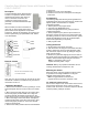
Table Of Contents

ClareOne Door Window Sensor with External Contact Installation Manual
CLR-C1-DWCNT
CLR-C1-DWCNT IM V3 05012020
Description
The Door/Window Sensor with Extended
Contact is a supervised, wireless sensor
that detects the opening and closing of
doors or windows. The sensor and
magnet are mounted using screws
(included) or double-sided adhesive tape
(included).
When activated, the sensor transmits an
open (trip) or close (restore) signal to the
panel. These are the signals the unit provides:
supervisory, tamper and low battery (as needed). The
sensor is powered by (2) replaceable 3-VDC, lithium
coin-cell batteries.
External Contact
Note: Only one set of contacts can be used at one time
the internal or external, for added security the internal
reed switch can be cut.
Installation Guidelines
1. Remove the transmitter’s cover by pressing in on the
small rectangular latch on the end of the cover and lift
up.
2. Mount the sensor base directly to the surface using
the mounting tape provided. Make sure to align the
mounting tape with the tamper pull put area on the
bottom of the sensor to insure proper tamper operation.
3. Mount the magnet next to the sensor and align the
magnet with the mark on the side of the sensor, using
the mounting tape provided, or connect an external
contact to the terminals.
4. Remove the battery isolator tabs from both batteries
on the sensor.
5. Replace the cover on the transmitter.
6. Enroll the senor into the control panel according the
instructions.
Programming
The following steps describe the general guidelines for
programming the sensor into panel memory. Refer to the
specific panel’s documentation for complete
programming details.
1. Set the panel to the program mode.
2. Proceed to the SENSORS menu.
3. Select the appropriate sensor group and sensor
number assignments.
4. When prompted by the panel to trip the sensor for
learning by remove the sensor cover and if present pull
the battery pull tabs or enter the sensor ID#. The system
should acknowledge the sensor by touchpad display
and/or audio (depending on the panel).
5. Exit program mode.
Testing the Sensor
1. Set the panel to the sensor test mode.
2. Take the sensor and magnet to the desired mounting
location, making sure to line up their alignment marks
with each other. Trip the sensor by pulling the magnet
away from the sensor.
3. Monitor the system after tripping the sensor. Refer to
the specific panel documentation for interpretation of the
results to ensure desired signal strength is achieved.
Note: If a low battery alarm occurs,
replace the battery within 7 days.
CAUTION: Battery may explode if mistreated. Do not
recharge, disassemble or dispose of in fire.
Mounting the Sensor
Mount the sensor using the supplied mounting screws
for permanent mounting installations or using the
supplied double-sided tape is optional.
Note: The gap between the sensor and
magnet should not exceed a maximum of 5/8”.
For Additional Tamper Security
Punch out the tamper cover on the bottom of the sensor,
and using the small screw secure it to the mounting
location, when the sensor is removed “tampered” the tab
remains providing a tamper condition.
Tamper
switch
Cover
Latch
Batteries
Terminals
Cover
Latch
Tamper
Base
Note: Do not exceed 50ft when wiring
to an external contact