
Specifications
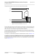
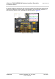
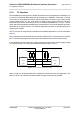
Table Of Contents
- Contents
- Tables
- Figures
- 1 Introduction
- 2 Interface Characteristics
- 2.1 Application Interface
- 2.2 RF Antenna Interface
- 2.3 GNSS Interface
- 2.4 Sample Application
- 3 Operating Characteristics
- 3.1 Operating Modes
- 3.2 Power Up/Power Down Scenarios
- 3.3 Power Saving
- 3.4 Power Supply
- 3.5 Operating Temperatures
- 3.6 Electrostatic Discharge
- 3.7 Blocking against RF on Interface Lines
- 3.8 Reliability Characteristics
- 4 Mechanical Dimensions, Mounting and Packaging
- 5 Regulatory and Type Approval Information
- 6 Document Information
- 7 Appendix

Cinterion
®
EXS62-W/EXS82-W Hardware Interface Description
2.1 Application Interface
61
t EXS62-W_EXS82-W_HID_v01.200ee 2022-09-07
Public/ Released
Page 36 of 144
In case the module is mounted onto the LGA DevKit, a direct connection to the eUICC can be
achieved by bridging the following pads on the backside of the LGA DevKit: PAD 249 to 17,
PAD 248 to 19, PAD 247 to 21, PAD 246 to 20, as also shown in Figure 15.
Figure 15: Interface bridging