Installation and Upgrade Guide for Cisco Unified Videoconferencing 3522 BRI Gateway and 3527 PRI Gateway Release 5.6 August 2008 Americas Headquarters Cisco Systems, Inc. 170 West Tasman Drive San Jose, CA 95134-1706 USA http://www.cisco.
THE SPECIFICATIONS AND INFORMATION REGARDING THE PRODUCTS IN THIS MANUAL ARE SUBJECT TO CHANGE WITHOUT NOTICE. ALL STATEMENTS, INFORMATION, AND RECOMMENDATIONS IN THIS MANUAL ARE BELIEVED TO BE ACCURATE BUT ARE PRESENTED WITHOUT WARRANTY OF ANY KIND, EXPRESS OR IMPLIED. USERS MUST TAKE FULL RESPONSIBILITY FOR THEIR APPLICATION OF ANY PRODUCTS.
CONTENTS CHAPTER 1 Functionality 1-1 About Cisco Unified Videoconferencing 3500 Gateway Products About Gateway Features 1-1 1-2 About Cisco Unified Videoconferencing 3500 Gateway Applications and Topologies About Multimedia Conferencing 1-6 About Point-to-Point Conferencing 1-7 About Multipoint Conferencing 1-7 About Gateway IP Network Connections 1-8 About Gateway ISDN Network Connections 1-8 About Cisco Unified Videoconferencing 3500 Gateway Functionality About PRI Gateway Call Handling Capacity 1-
Contents SNMP Management 2-11 Local Port Monitoring Connections 2-11 Performing Software Upgrades 2-12 Accessing the Cisco Unified Videoconferencing 3500 Gateway Administrator Interface 2-12 Online Help Registration 2-13 Netscape Navigator Users 2-13 CHAPTER 3 Using the Cisco Software Upgrade Utility 3-1 About the Cisco Software Upgrade Utility 3-1 Launching the Cisco Software Upgrade Utility Upgrading Software CHAPTER 4 3-2 Cable Connections and Pin-outs RS-232 9-Pin Serial Port 4-1 4-1 RJ
Contents Procedimientos ESD Securite 6-5 6-6 Securite Electrique 6-6 Mise a la Terre 6-6 Haute Tension 6-7 Prevention des Decharges Electrostatiques CHAPTER 7 Compliance and Certifications Safety Compliance 6-7 7-1 7-1 EMC 7-1 FCC Part 15 Notice 7-2 Telecom 7-2 ACTA Part 68 Notice 7-2 Industry Canada 7-3 Environmental Compliance 7-3 INDEX Installation and Upgrade Guide for Cisco Unified Videoconferencing 3522 BRI Gateway and 3527 PRI Gateway Release 5.
Contents Installation and Upgrade Guide for Cisco Unified Videoconferencing 3522 BRI Gateway and 3527 PRI Gateway Release 5.
CH A P T E R 1 Functionality • About Cisco Unified Videoconferencing 3500 Gateway Products, page 1-1 • About Gateway Features, page 1-2 • About Cisco Unified Videoconferencing 3500 Gateway Applications and Topologies, page 1-6 • About Cisco Unified Videoconferencing 3500 Gateway Functionality, page 1-11 About Cisco Unified Videoconferencing 3500 Gateway Products The Cisco Unified Videoconferencing 3500 Gateway series consists of these products: • Cisco Unified Videoconferencing 3527 PRI Gateway T
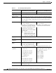
Chapter 1 Functionality About Gateway Features About Gateway Features Table 1-1 lists the major features of the Cisco Unified Videoconferencing 3500 Gateway. Table 1-1 Gateway Feature Summary Feature Description Interoperability The gateway provides a high degree of interoperability with other H.323 compliant gateways, gatekeepers, terminals, proxy, and Multipoint Control Unit (MCU) products by being based on the H.320 standard and H.323 protocol stack.
Chapter 1 Functionality About Gateway Features Table 1-1 Gateway Feature Summary (continued) Feature Description Dual video The gateway supports H.239 standards-based dual video and TANDBERG DuoVideo technology. Dual video streams enable a screen to carry video images from one source while simultaneously displaying images from a second source.
Chapter 1 Functionality About Gateway Features Table 1-2 Cisco Gateway Feature Specifics Feature Cisco Unified Videoconferencing 3527 PRI Gateway Cisco Unified Videoconferencing 3522 BRI Gateway Supported ports 1 PRI ISDN port 4 BRI ISDN ports Supported video H.320, H.323 (using Cisco Stack v4.0) conferencing protocols Supported audio codecs The term audio transcoded video calls refers to the process whereby an audio stream in a multimedia call can be transcoded from one codec type to another.
Chapter 1 Functionality About Gateway Features Table 1-2 Cisco Gateway Feature Specifics (continued) Feature Cisco Unified Videoconferencing 3527 PRI Gateway Cisco Unified Videoconferencing 3522 BRI Gateway IP network connection I10/100Base-T Ethernet IP UTP connection (on the front panel). Serial control port (DB-9) connection RS-232 DTE 9-pin D-type connection on front panel for connection to a PC terminal or an external modem.
Chapter 1 Functionality About Cisco Unified Videoconferencing 3500 Gateway Applications and Topologies About Cisco Unified Videoconferencing 3500 Gateway Applications and Topologies • About Multimedia Conferencing, page 1-6) • About Point-to-Point Conferencing, page 1-7) • About Multipoint Conferencing, page 1-7) • About Gateway IP Network Connections, page 1-8) • About Gateway ISDN Network Connections, page 1-8) About Multimedia Conferencing The Cisco PRI gateway and BRI gateway enable H.
Chapter 1 Functionality About Cisco Unified Videoconferencing 3500 Gateway Applications and Topologies About Point-to-Point Conferencing The Cisco BRI gateway enables direct video, voice, and data communication between an H.320 (ISDN) terminal and H.323 (IP) terminals at bandwidths of up to 512 Kbps (4 BRI lines) using bonding mode 1 (see Figure 1-2). The Cisco PRI gateway enables direct video, voice, and data communication between an H.320 (ISDN) terminal and H.
Chapter 1 Functionality About Cisco Unified Videoconferencing 3500 Gateway Applications and Topologies Figure 1-3 Mixed ISDN-IP Multipoint Multimedia Conference IP network H.323 Terminal IP H.320 Terminal IP phone H.323 Terminal H.323 Terminal H.323 Terminal ISDN Cisco Unified Videoconferencing Gateway Cisco Unified Videoconferencing MCU H.320 Terminal H.320 Terminal H.
Chapter 1 Functionality About Cisco Unified Videoconferencing 3500 Gateway Applications and Topologies PRI Gateways You can connect the PRI gateway directly to a PRI line provided by your local ISDN provider (as shown in Figure 1-4), or to a local private branch exchange (PBX) that provides the PRI connection (as shown in Figure 1-5). Figure 1-4 Connecting the PRI Gateway Directly to a Central Office Switch Private Public IP network PRI T1/E1 H.
Chapter 1 Functionality About Cisco Unified Videoconferencing 3500 Gateway Applications and Topologies BRI Gateways You can connect the BRI gateway to a local private branch exchange (PBX) that provides the BRI connection (as shown in Figure 1-6), or to a public phone network using an NT1 device (as shown in Figure 1-7). Figure 1-6 Connecting the BRI Gateway Directly to a PBX that Provides a BRI Line Private Public H.
Chapter 1 Functionality About Cisco Unified Videoconferencing 3500 Gateway Functionality About Cisco Unified Videoconferencing 3500 Gateway Functionality • About PRI Gateway Call Handling Capacity, page 1-11 • About BRI Gateway Call handling Capacity, page 1-11 • About Gateway Call Bandwidth Overhead, page 1-12 • About Peer-to-Peer Connectivity, page 1-12 About PRI Gateway Call Handling Capacity Table 1-3 lists the maximum call handling capacity of the PRI gateway for different types of calls.
Chapter 1 Functionality About Cisco Unified Videoconferencing 3500 Gateway Functionality About Gateway Call Bandwidth Overhead According to the H.320 standard, the available bandwidth allocated to a call at any given bit rate will always be slightly less than the stated maximum for the following reasons: • All stated maximum call bandwidths include provision for control, audio, video, and data traffic.
CH A P T E R 2 Setting Up Your Cisco Unified Videoconferencing 3500 Gateway • Physical Description, page 2-1 • Requirements for Installing of the Cisco Unified Videoconferencing 3527 PRI Gateway, page 2-3 • Preparing for Installation of the Cisco Unified Videoconferencing 3522 BRI Gateway, page 2-4 • Verifying the Package Contents, page 2-5 • Mounting the Cisco Unified Videoconferencing 3500 Gateway Unit in a 19-inch Rack, page 2-5 • How to Perform the Cisco Unified Videoconferencing 3500 Gatew
Chapter 2 Setting Up Your Cisco Unified Videoconferencing 3500 Gateway Physical Description Front Panel Figure 2-1 shows the front panel of the Cisco Unified Videoconferencing 3500 Gateway unit. Table 2-1 describes the components of the front panel.
Chapter 2 Setting Up Your Cisco Unified Videoconferencing 3500 Gateway Requirements for Installing of the Cisco Unified Videoconferencing 3527 PRI Gateway Table 2-2 Cisco Unified Videoconferencing 3527 PRI Gateway Rear Panel Components Component Description ACT LED Lights green to indicate that there are active calls in the gateway. D-Ch LED Lights green to indicate that the PRI line is enabled and a carrier signal is detected. ALARM LED Displays alarm events for the PRI line.
Chapter 2 Preparing for Installation of the Cisco Unified Videoconferencing 3522 BRI Gateway Setting Up Your Cisco Unified Videoconferencing 3500 Gateway • The IP address of the router that the Cisco Unified Videoconferencing 3527 PRI Gateway unit will use to communicate across the network • For an H.323 environment, the IP address of the H.
Chapter 2 Setting Up Your Cisco Unified Videoconferencing 3500 Gateway Verifying the Package Contents • Key Hold • ACO Verifying the Package Contents Procedure Step 1 Inspect the contents of the box for shipping damage. Step 2 Report any damage or missing items to your Cisco representative. Step 3 Verify contents. SeeTable 2-4 lists the package contents for the Cisco Unified Videoconferencing 3500 Gateway unit.
Chapter 2 Setting Up Your Cisco Unified Videoconferencing 3500 Gateway How to Perform the Cisco Unified Videoconferencing 3500 Gateway Unit Initial Configuration Fitting a Bracket for Rack Mounting 157263 Figure 2-4 Step 4 Pass the screws through the brackets and tighten them into the screw holes on each side of the Cisco Unified Videoconferencing 3500 Gateway unit using a suitable screwdriver. Step 5 Insert the Cisco Unified Videoconferencing 3500 Gateway unit into the 19-inch rack.
Chapter 2 Setting Up Your Cisco Unified Videoconferencing 3500 Gateway How to Perform the Cisco Unified Videoconferencing 3500 Gateway Unit Initial Configuration Note You can perform serial port configuration of the Cisco Unified Videoconferencing 3500 Gateway unit only at startup, during a short period indicated by a 6-second countdown. Once the initialization phase is complete, the only way you can access the configuration menu is by restarting the Cisco Unified Videoconferencing 3500 Gateway unit.
Chapter 2 Setting Up Your Cisco Unified Videoconferencing 3500 Gateway How to Perform the Cisco Unified Videoconferencing 3500 Gateway Unit Initial Configuration Procedure Step 1 Connect the supplied terminal cable to the PC terminal. Step 2 Connect the power cable. Step 3 Start the terminal emulation application on the PC.
Chapter 2 Setting Up Your Cisco Unified Videoconferencing 3500 Gateway How to Perform the Cisco Unified Videoconferencing 3500 Gateway Unit Initial Configuration • Convert the subnet mask IP address to hexadecimal notation, type the hexadecimal number at the prompt, and press Enter. For example, for the subnet mask 255.255.255.0 the hexadecimal value you type is FFFFFF00. Note • You can use the computer’s desktop calculator to convert the subnet mask ID to hexadecimal notation.
Chapter 2 Setting Up Your Cisco Unified Videoconferencing 3500 Gateway How to Perform the Cisco Unified Videoconferencing 3500 Gateway Unit Initial Configuration The network configuration Main menu appears. Step 7 At the Network Configuration menu, do one of the following: • Enter the letter for the set of parameters that you want to configure. • Enter Q to save your changes and allow the device to complete the boot process.
Chapter 2 Setting Up Your Cisco Unified Videoconferencing 3500 Gateway Connecting the Cisco Unified Videoconferencing 3500 Gateway Unit to the LAN Connecting the Cisco Unified Videoconferencing 3500 Gateway Unit to the LAN Procedure Step 1 Connect the supplied LAN cable from your network hub to the 10/100BaseT Ethernet port on the front panel of the Cisco Unified Videoconferencing 3500 Gateway unit. The 10/100BaseT port accepts an RJ-45 connector.
Chapter 2 Accessing the Cisco Unified Videoconferencing 3500 Gateway Administrator Interface Setting Up Your Cisco Unified Videoconferencing 3500 Gateway Performing Software Upgrades You can perform software upgrades by using the Cisco Upgrade Utility to upload files via a network or modem connection to the Cisco Unified Videoconferencing 3500 Gateway unit. For more information, see Chapter 3, “Using the Cisco Software Upgrade Utility”.
Chapter 2 Setting Up Your Cisco Unified Videoconferencing 3500 Gateway Online Help Registration Note If you try to sign in as an Administrator and another Administrator is currently signed in, the Cisco Unified Videoconferencing 3500 Gateway signs you in as a Read only user and the words Read Only appear at the top of the window. Read only users cannot edit any of the Cisco Unified Videoconferencing 3500 Gateway settings.
Chapter 2 Setting Up Your Cisco Unified Videoconferencing 3500 Gateway Online Help Registration Installation and Upgrade Guide for Cisco Unified Videoconferencing 3522 BRI Gateway and 3527 PRI Gateway Release 5.
CH A P T E R 3 Using the Cisco Software Upgrade Utility • About the Cisco Software Upgrade Utility, page 3-1 • Launching the Cisco Software Upgrade Utility, page 3-1 • Upgrading Software, page 3-2 About the Cisco Software Upgrade Utility The Cisco Software Upgrade Utility is an interactive GUI interface that enables you to upgrade Cisco software installed on Cisco devices.
Chapter 3 Using the Cisco Software Upgrade Utility Upgrading Software Upgrading Software You use the Software Upgrade Utility to upgrade Cisco software installed on Cisco devices. Procedure Step 1 In the General Information section of the Upgrade Utility dialog box, enter the IP address of the device you want to upgrade. Step 2 In the Login Information section, enter the administrator user name and password for the target device, as configured in the device network configuration settings.
CH A P T E R 4 Cable Connections and Pin-outs • RS-232 9-Pin Serial Port, page 4-1 • RJ-45 8-Pin IP Network Port, page 4-1 • ISDN Port, page 4-2 RS-232 9-Pin Serial Port Table 4-1 describes the Cisco Unified Videoconferencing 3500 Gateway unit RS-232 9-pin D-type serial port pin-out configuration.
Chapter 4 Cable Connections and Pin-outs ISDN Port Table 4-2 Pin-out Configuration of the RJ-45 IP Network Port 3 RXD+ 4 NC 5 NC 6 RXD- 7 NC 8 NC Input Input ISDN Port Table 4-3 describes the ISDN Port RJ-45 connector pin-out configuration. Table 4-3 ISDN Port RJ-45 Connector Pin-out Pin Function 1 RXD + 2 RXD - 3 NC 4 TXD + 5 TXD - 6 NC 7 NC 8 NC Installation and Upgrade Guide for Cisco Unified Videoconferencing 3522 BRI Gateway and 3527 PRI Gateway Release 5.
CH A P T E R 5 Technical Specifications Table 5-1 Cisco Unified Videoconferencing 3500 Gateway Unit Technical Specifications Unit Dimensions • Height: 1U (1.75 inches or 44.45 mm) • Width: 17.25 inches (438.15 mm) • Depth: 10 inches (254 mm) • Weight: 4.45 kg (9.
Chapter 5 Table 5-1 Technical Specifications Cisco Unified Videoconferencing 3500 Gateway Unit Technical Specifications (continued) Rear panel (Cisco Unified Videoconferencing 3527 PRI Gateway) • 1 x ISDN E1/T1 PRI port: – T1 mode Channels: 23B + 1D Clock rate: 1.544 Mbps Framing: ESF or D4 Encoding: B8ZS or AMI Line impedance: 100Ω – E1 mode Channels: 30B + 1D Clock rate: 2.048 Mbps Framing: G.
CH A P T E R 6 Safety • Electrical Safety, page 6-1 • ESD Procedures, page 6-2 Electrical Safety To avoid an electric shock or damage to the Cisco Unified Videoconferencing 3500 Gateway unit, servicing should be performed by qualified service personnel only. To reduce the risk of damaging power surges, Cisco recommends installing an AC surge arrestor in the AC outlet from which the Cisco Unified Videoconferencing 3500 Gateway unit is powered.
Chapter 6 Safety ESD Procedures Laite on liitettävä suojamaadoituskoskettimilla varustettuun pistorasiaan. Apparatet må tilkoples jordet stikkontakt. Apparaten skall anslutas till jordat uttag. High Voltage Disconnect the Cisco Unified Videoconferencing 3500 Gateway unit from the power line before removing the cover. Avoid any adjustment, maintenance, or repair of an opened chassis under voltage. These actions should only be carried out by a skilled person who is aware of the dangers involved.
Chapter 6 Sicherheit Elektrische Sicherheit Sicherheit Dieses Kapitel beschreibt die Sicherheitsvorschriften und -vorgaben zur Bedienung der Cisco Unified Videoconferencing 3515-Plattform einschließlich des Folgenden: • Elektrische Sicherheit, page 6-3 • ESD-Verfahren, page 6-3 • Warnhinweise, page 6-3 Elektrische Sicherheit Zur Vermeidung eines elektrischen Schlags oder Schäden an der Cisco Unified Videoconferencing 3515-Plattform darf die Wartung von qualifiziertem Fachpersonal vorgenommen werden.
Chapter 6 Seguridad Seguridad Electrica Seguridad Electrica Para evitar una sacudida eléctrica o daños en la unidad Cisco Unified Videoconferencing 3515, las reparaciones deberán ser realizadas sólo por personal técnico calificado. Para reducir el riesgo de las sobretensiones, Cisco recomienda instalar un protector contra sobretensiones de CA en la salida de CA que alimenta a la unidad Cisco Unified Videoconferencing 3515. No intente abrir la unidad Cisco Unified Videoconferencing 3515.
Chapter 6 Seguridad Securite Electrique Securite Cette section décrit les procédures et les exigences en matière de sécurité concernant la mise en exploitation de la Cisco Unified Videoconferencing 3515.
Chapter 6 Seguridad Prevention des Decharges Electrostatiques En Suède et en Finlande, l’installation ne doit se faire que dans des zones à accès contrôlé. Haute Tension Débranchez l’unité Cisco Unified Videoconferencing 3515 de la prise électrique avant d’enlever le couvercle. Évitez toute intervention, opération d’entretien ou réparation sur un châssis ouvert sous tension. Ces actions ne devraient être effectuées que par une personne expérimentée et connaissant les dangers encourus.
CH A P T E R 7 Compliance and Certifications • Safety Compliance, page 7-1 • EMC, page 7-1 • Telecom, page 7-2 • Environmental Compliance, page 7-3 Safety Compliance The Cisco Unified Videoconferencing 3500 Gateway unit supports these safety standards: • UL 60950 • CSA C22.2 No.
Chapter 7 Compliance and Certifications Telecom Warning • EN 61000-3-3 • EN 61000-6-1 This is a class A product. In a domestic environment this product may cause radio interference in which case the user may be required to take adequate measures. FCC Part 15 Notice This section provides RF interference information for the user. This equipment has been tested and found to comply with the limits for a Class A digital device, pursuant to Part 15 of the FCC rules.
Chapter 7 Compliance and Certifications Environmental Compliance Step 5 The telephone company may make changes in its facilities, equipment, operations or procedures that could affect the operation of the equipment. If this happens, the telephone company will provide advance notice in order for you to make necessary modifications to maintain uninterrupted service.
Chapter 7 Compliance and Certifications Environmental Compliance Installation and Upgrade Guide for Cisco Unified Videoconferencing 3522 BRI Gateway and 3527 PRI Gateway Release 5.
INDEX RS-232 9-pin serial port A call bandwidth overhead access control ACT LED 1-2 BRI gateway capacity Administrator interface 2-12 capabilities Advanced Configuration menu ALRM LED 2-2, 2-3 audio codecs 1-4 auto-boot 1-12 call handling 2-2, 2-3 audio transcoding 4-1 2-9 1-11 1-4 PRI gateway capacity 1-11 Certifications EMC 1-4 7-1 Telecom 2-6 chipset 7-2 5-2 communication interfaces conceal caller ID B 5-1 1-3 connectors bandwidth call overhead 1-12 resource allocat
Index installation requirements E interoperability E1/T1 EMC 1-8, 1-12 1-2 IP address assign 7-1 2-3 2-7 IP network connection encryption 1-3 1-3, 1-5 ISDN Ethernet connection failure 10/100Base-T connector speed 1-5 rollover 2-2 IVR 2-9 1-3 1-2 internal capacity Ethernet LED 1-3 1-5 2-2 L F LAN failsafe 5-2 fast start 10/100Base-T 1-3 LED indicators feature summary line quality general features specific 1-2 1-5 2-2, 2-3, 5-1 1-4 local 1-4 configuration first-ti
Index requirements P 2-7 installation package contents 2-5 RJ-45 password 2-2, 2-3, 2-11 rollover default login user 2-10 routing peer-to-peer 2-3 1-3 1-2 RS-232 connectivity 1-3, 1-12 DTE 9-pin D-type connection pin-out configuration RST button RJ-45 IP network port 1-5 2-2, 5-1 4-1 RS-232 9-pin D-type serial port point-to-point conferencing 4-1 S 1-7 ports Safety RJ-45 IP 4-1 compliance RS-232 9-pin serial SVGA 4-1 electrical 2-12 power supply Prevention 6-1 ESD pr
Index T T.120 data collaboration TCS4 1-2 1-2 Telecom 7-2 U unit dimensions upgrade software 5-1 3-1 V video conferencing protocols video protocols video resolutions 1-4 1-4 1-4 W web-based management 1-2 Installation and Upgrade Guide for Cisco Unified Videoconferencing 3522 BRI Gateway and 3527 PRI Gateway Release 5.