Cisco Video Surveillance 5010/5011 Indoor Fixed HD IP Dome Camera User Guide Americas Headquarters Cisco Systems, Inc. 170 West Tasman Drive San Jose, CA 95134-1706 USA http://www.cisco.
THE SPECIFICATIONS AND INFORMATION REGARDING THE PRODUCTS IN THIS MANUAL ARE SUBJECT TO CHANGE WITHOUT NOTICE. ALL STATEMENTS, INFORMATION, AND RECOMMENDATIONS IN THIS MANUAL ARE BELIEVED TO BE ACCURATE BUT ARE PRESENTED WITHOUT WARRANTY OF ANY KIND, EXPRESS OR IMPLIED. USERS MUST TAKE FULL RESPONSIBILITY FOR THEIR APPLICATION OF ANY PRODUCTS.
CONTENTS Preface CHAPTER 1 vii Introduction Models 1-1 1-1 Getting Started 1-1 Parts List 1-2 Product Overview 1-2 Product Label 1-4 CHAPTER 2 Installation 2-1 In-Ceiling Installation Surface Installation 2-1 2-4 Dome Liner and Lower Dome Installation Service Cable 2-7 2-9 Wiring 2-10 Cat5 or Cat6 Cable 2-10 24 VAC Connector 2-11 Single Camera Wiring 2-11 Multiple Camera Wiring 2-12 Alarm and Relay Connector 2-12 Connecting a Relay Device 2-13 Connecting Alarms 2-13 CHAPTER 3 Operation 3
Contents Unicast 3-5 Taking a Snapshot 3-6 Displaying Video in the Multiscreen View Settings Page 3-6 Accessing the Camera Menus 3-6 3-7 System Tab 3-7 Changing the Device Name 3-7 Configuring the Time Settings 3-8 Customizing the Appearance of the Text Overlay Generating a System Log 3-9 Rebooting the Camera 3-9 Restoring All Camera Defaults 3-9 3-8 Network Tab 3-9 Changing the Hostname 3-10 Turning On DHCP 3-10 Turning Off DHCP 3-11 Imaging Tab 3-11 Configuring the Orientation of the Scene 3-13 Chan
Contents Bit Rate 3-28 Quality of Service for Differentiated Services Code Point Rate Control 3-29 Profile 3-29 Advance Sharpening 3-30 3-28 Users and Groups Tab 3-30 Creating a New User 3-31 Editing a User 3-32 Deleting a User 3-32 Creating a New Group 3-33 Editing a Group 3-33 Deleting a Group 3-33 General Settings for Users and Groups 3-34 Setting the Camera to Node 3-34 Setting the Camera to Mixed 3-35 Events Tab 3-35 Sources 3-36 Creating an Alarm Event Source 3-36 Creating a System Event Source 3-3
Contents Cisco Video Surveillance 5010/5011 Indoor Fixed HD IP Dome Camera User Guide vi OL-22669-02
Preface Obtaining Documentation and Submitting a Service Request For information on obtaining documentation, submitting a service request, and gathering additional information, see the monthly What’s New in Cisco Product Documentation, which also lists all new and revised Cisco technical documentation, at: http://www.cisco.com/en/US/docs/general/whatsnew/whatsnew.
Preface Cisco Video Surveillance 5010/5011 Indoor Fixed HD IP Dome Camera User Guide viii OL-22669-02
CH A P T E R 1 Introduction The 5010/5011 cameras are fixed network dome cameras with a built-in Web-based viewer for live streaming to a standard Web browser (Microsoft Internet Explorer 8). The cameras support standard H.264 and MJPEG compression formats and dual video streams that can be configured for a variety of resolutions, frame rates, and bit rates. Each camera also includes a 2.
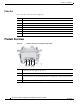
Chapter 1 Introduction Product Overview Parts List Remove all of the contents from the shipping box.
Chapter 1 Introduction Product Overview Figure 1-2 Camera Connections and Features (Top View) 1 3 5 6 8 9 7 278771 2 4 1 Reset Button: Reboots the camera or restores the camera’s factory default settings. This button is recessed. Using a small tool, such as a paper clip, press and release the reset button once to reboot the camera. Press and hold the reset button for 10 seconds to restore the camera to the factory default settings.
Chapter 1 Introduction Product Overview Product Label The product label lists the model number, date code, serial number, and Media Access Control (MAC) address. This information might be required for setup. The product label is located on the side of the back box.
CH A P T E R 2 Installation You can install the 5010/5011 network dome camera using one of the following methods: • Installation in a suspended ceiling or a fixed ceiling/wall (refer to “In-Ceiling Installation” section on page 2-1). • Mounting to the surface of a ceiling/ wall (refer to “Surface Installation” section on page 2-4). In-Ceiling Installation Warning Step 1 Step 2 Remove the foam insert from the back box before installing the system.
Chapter 2 Installation In-Ceiling Installation c. Connect the auto iris lens to the 4-pin connector located on the side of the camera. Pin connections for the iris drive connector are as follows: Figure 2-1 Lens Pin Connections 4 1 2 Pin DC (AID) Auto Iris Lens 1 Control coil negative (–) 2 Control coil positive (+) 3 Drive coil positive (+) 4 Drive coil negative (–) 278768 3 Step 3 Step 4 Connect the wiring to the side of the back box: a.
Chapter 2 Installation In-Ceiling Installation Step 6 Position the camera: a. View the camera image using the service jack or a Web browser. b. Unlock the tab locks located on each side of the camera. c. Manually rotate and tilt the camera module to position the camera. Do not over-rotate the module. d. Lock the tab locks to secure the camera. Figure 2-3 Positioning the Camera 1 2 279055 3 4 Step 7 Step 8 1 Pan 368° 3 Rotate 355° 2 Tab lock 4 Tilt 180° Focus the lens: a.
Chapter 2 Installation Surface Installation Surface Installation Warning Step 1 Remove the foam insert from the back box before installing the system. The foam is inserted to secure the tilt ring; preventing damage to the optical chassis during shipment. Prepare the mounting surface: a. Using the surface mount ring as a template, drill holes for the mounting hardware.
Chapter 2 Installation Surface Installation Step 3 Step 4 Connect the wiring to the side of the back box: a. Plug the network cable into the RJ-45 connector on the side of the camera. If the network has no PoE, connect a 24 VAC Class 2 power supply to the 24 VAC power connector. Refer to “Wiring” section on page 2-10 for wiring connections. b. Connect the necessary wiring for alarms and relays (refer to “Wiring” section on page 2-10 for more information).
Chapter 2 Installation Surface Installation Figure 2-6 Positioning the Camera 1 2 279055 3 4 Step 7 Step 8 1 Pan 368° 3 Rotate 355° 2 Tab lock 4 Tilt 160° Focus the lens: a. View the camera image using the service jack or a Web browser. b. Press the auto back focus button once to center the focus mechanism. The button is located on the rim of the back box. c.
Chapter 2 Installation Dome Liner and Lower Dome Installation Dome Liner and Lower Dome Installation Step 1 Align the magnets on the dome liner with the magnets located on the camera module. Installing the Dome Liner 279051 Figure 2-7 Step 2 Attach the leash of the lower dome to the back box. Attaching the Leash 279056 Figure 2-8 Step 3 Warning Move the lower dome latches away from the bubble until you hear a click indicating the latches are open.
Chapter 2 Installation Dome Liner and Lower Dome Installation Aligning the Lower Dome with Camera 279052 Figure 2-9 Step 4 Move the lower dome latches toward the bubble until you hear a click. Locking the Dome 279053 Figure 2-10 Step 5 Turn the top cover of the lower dome 90-degrees to conceal the camera latches, LED, and service jack.
Chapter 2 Installation Service Cable Service Cable The dome camera includes a service port that outputs camera video. Use it at the installation site to set up the field of view and to focus the camera. To assemble a service cable for the camera, you will need to purchase the following items from an electronics supply store: Qty Description 1 2.
Chapter 2 Installation Wiring Attaching the 2.5 mm Monaural Headphone Plug 1 8 7 6 5 2 3 278793 Figure 2-12 4 1 2.5 mm Stereo Plug 5 Shrink Fit Tubing 2 Plug Shoulder Pin 6 Coaxial Cable 3 Center Conductor 7 Coaxial Braid Shield 4 Support Sleeve 8 Crimp Pin Arm Wiring Cat5 or Cat6 Cable Connect a Cat5 or Cat 6 cable to the RJ-45 network port. The 8-pin connector includes video and PoE for the camera. PoE (IEEE 802.
Chapter 2 Installation Wiring Refer to Figure 2-13 for pin descriptions. Figure 2-13 Cat5 or Cat6 Cable Pin Descriptions 1 1 2 3 4 5 6 7 8 8 8 8 1 7 6 5 4 3 2 279057 1 Pin Function 1 TX+ 2 TX– 3 RX+ 4 PoE 1-2 5 PoE 1-2 6 RX– 7 PoE 3-4 8 PoE 3-4 24 VAC Connector Single Camera Wiring If PoE is not available: Step 1 Connect the 24 VAC wires to the supplied 2-pin connector (refer to Figure 2-14). Note Step 2 Only use the 24 VAC wires if PoE is not available.
Chapter 2 Installation Wiring Figure 2-14 24 VAC Connector 279084 24V~ Multiple Camera Wiring If you are operating the camera using 24 VAC and you are wiring more than one camera to the same transformer: Step 1 Connect one side of the transformer to pin 1 of the 2-position terminal block on all modules. Step 2 Connect the other side of the transformer to pin 2 of the terminal block on all modules.
Chapter 2 Installation Wiring Figure 2-15 Alarm and Relay Connector 2790893 RELAY R1 ALARM A1 Connecting a Relay Device The camera has an output for activating an external device. It supports both momentary and continuous relay operation. You can operate the relay interactively during an active connection, or it can operate automatically to coincide with certain events. Typical applications include turning on lights or other electrical devices or activating a door, gate, or lock.
Chapter 2 Installation Wiring Note Install the 1-kohm resistor as close to the switch as possible. Figure 2-17 illustrates the alarm and no alarm conditions of a supervised alarm input. Whether the alarm is normally closed or normally open, neither a cut nor a bypass can defeat these alarms.
Chapter 2 Installation Wiring Unsupervised Alarm Conditions NORMALLY CLOSED NO ALARM GND +v NORMALLY OPEN NO ALARM GND +v Alarm GND +v Alarm GND Alarm GND +v No Alarm GND Cut No Alarm GND +v +v Cut Alarm GND +v +v Bypass Bypass 278792 Figure 2-19 Figure 2-20 illustrates the wiring configuration for unsupervised alarm inputs.
Chapter 2 Installation Wiring Cisco Video Surveillance 5010/5011 Indoor Fixed HD IP Dome Camera User Guide 2-16 OL-22669-02
CH A P T E R 3 Operation Camera Configuration Sequence Once the camera is installed and power is applied, the camera will start a configuration sequence: the green LED flashes five times per second for approximately two minutes and then glows solid green, indicating that the boot cycle is complete and the camera is on line. Note If the camera is not connected to a Dynamic Host Configuration Protocol (DHCP) server and DHCP is enabled, the configuration sequence might take up to five minutes to complete.
Chapter 3 Operation Accessing the IP Camera Note This product is not compatible with QuickTime version 7.6.4 for Windows XP, Windows Vista. If you have this version installed on your PC, upgrade to QuickTime version 7.6.5. Refer to the following sections for more information: • Compression Standards, page 3-28 • Available Camera Resolution, page 3-28 • Image Rate, page 3-28 • Bit Rate, page 3-28 Accessing the IP Camera The first time you access the camera, the live video page appears.
Chapter 3 Operation Live Video Page Refer to the following section for more information: • Editing a User, page 3-32 Live Video Page The live video page allows you to manage the way you view live video and capture images. You can also view live video from this page and access menus on the navigation bar (based on user permissions).
Chapter 3 Operation Live Video Page 1 x 1 Mode: Displays a single video pane. 2 x 2 Mode: Displays 4 video panes in rows of two. 3 x 3 Mode (full-screen mode only): Displays 9 video panes in rows of three. 4 x 4 Mode (full-screen mode only): Displays 16 video panes in rows of four. Select Stream: Selects the viewable video stream that is displayed in live view (primary or secondary). Maximize Viewing Area: Scales the image to the full size of the browser.
Chapter 3 Operation Live Video Page Refer to the following sections for more information: • Primary Stream and Secondary Stream, page 3-5 • QuickView Stream, page 3-5 • Unicast, page 3-5 • Compression Standards, page 3-28 • Image Rate, page 3-28 Primary Stream and Secondary Stream The Primary Stream and Secondary Stream are video streams that include compression, resolution, image rate, and bit rate settings.
Chapter 3 Operation Settings Page Taking a Snapshot Step 1 Click the “Take a Snapshot” button. Step 2 The File Download dialog box opens, and the following message appears: “Do you want to open or save this file?” Step 3 Select one of the following options: • Open: Your computer’s photo editing program opens and displays the screen image. This function is available only when using Microsoft® Internet Explorer® 7.0 (or later) or Mozilla® Firefox® 3.0 (or later).
Chapter 3 Operation System Tab Accessing the Camera Menus Step 1 Log on to the camera. Step 2 Click the Settings link in the navigation bar located in the upper-right corner of the page; a list of menu tabs appears. Step 3 Place the mouse pointer over a tab to display a list of submenus.
Chapter 3 Operation System Tab Step 2 Click the Device Name box and highlight the text. Step 3 Type a user-friendly name into the Device Name box (2 to 64 characters). A user-friendly name makes it easier to recognize the device on the network. Examples of user-friendly names are Front Door, Lobby, or Parking Lot. Step 4 Click Save to save the new device name, or click Reset to restore to the previously saved device name.
Chapter 3 Operation Network Tab Step 5 Click the Save button to save the settings, or click the Reset button to clear all of the information you entered without saving it. Generating a System Log Step 1 Click the System tab. Step 2 Click the Generate System Log button to create a system log that can be used by technical support. Rebooting the Camera Step 1 Click the System tab. Step 2 Click the Reboot Camera button to restart the camera.
Chapter 3 Operation Network Tab General Network Settings The General Network page includes programmable and read-only fields for network communication settings. Available settings include the Hardware Address, Hostname, IP Address, Subnet Mask, Gateway, and DNS Servers. You can also enable or disable the Dynamic Host Configuration Protocol (DHCP) server from the General Network page. DHCP automatically assigns an IP address to the device if there is a DHCP server on the network.
Chapter 3 Operation Imaging Tab If the camera is not connected to a DHCP server but DHCP is set to On, the default IP address 192.168.0.20 on subnet mask 255.255.255.0 is automatically assigned to the camera. After the first camera is connected and assigned the default IP address, the system will automatically look for other cameras on the auto IP address system and assign IP addresses in sequential order as required.
Chapter 3 Operation Imaging Tab Digital processing settings can be set to Auto or Manual to adjust the camera’s sharpness, saturation, and contrast. When set to Auto, the camera continually delivers the best possible image by automatically adjusting the digital processing settings based on the scene. Auto is the default setting. Manual digital processing is recommended only for indoor applications that have a single, unchanging primary light source.
Chapter 3 Operation Imaging Tab • Configuring Auto Focus Settings, page 3-19 • Configuring Manual Focus Settings, page 3-20 • Setting Tone Map Options, page 3-21 • Selecting Auto White Balance Settings, page 3-22 • Selecting Manual White Balance Settings, page 3-23 • Turning On Window Blanking, page 3-24 • Turing Off Window Blanking, page 3-24 • Deleting a Window Blanking Area, page 3-25 Configuring the Orientation of the Scene Figure 3-2 Orientation Page Step 1 Place your mouse pointer
Chapter 3 Operation Imaging Tab Changing the Digital Processing Settings Figure 3-3 Digital Processing Page Step 1 Place your mouse pointer over the Imaging tab. Step 2 Select General from the drop-down menu. Step 3 Select the mode: Manual or Auto. Auto is the default. Step 4 Move the slider to the left or right to change the following settings: • Sharpness Adjust/Sharpness: Controls the clarity of detail in a scene.
Chapter 3 Operation Imaging Tab Selecting Auto Exposure Settings Figure 3-4 Auto Exposure Page Step 1 Place your mouse pointer over the Imaging tab. Step 2 Select Exposure from the drop-down menu. Step 3 Select the Auto mode. Step 4 Select the Light Control method: Digital Exposure or Auto-Iris Exposure. Step 5 • Digital Exposure: This setting automatically adjusts the sensor exposure time depending on the light level at the scene.
Chapter 3 Operation Imaging Tab Step 6 Set the Exposure Compensation setting. Move the slider bar to the right to brighten the video, or move it to the left to darken the video. The exposure compensation range is -100 to 100; the default setting is 0 (zero). Step 7 Set the Max Exposure Time and Night Max Exposure Time. Step 8 Step 9 Step 10 • Max Exposure Time: This setting controls the maximum time in milliseconds that an image is exposed during daytime conditions.
Chapter 3 Operation Imaging Tab Selecting Manual Exposure Settings Figure 3-5 Manual Exposure Page Step 1 Place your mouse pointer over the Imaging tab. Step 2 Select Exposure from the drop-down menu. Step 3 Select the Manual mode. Step 4 Move the Analog Gain slider to the desired position. Increasing the gain increases the brightness of the image, but it also increases the amount of noise in the image. The analog gain range is 1.00 to 15.75; the default setting is 1.00.
Chapter 3 Operation Imaging Tab Day Night Settings The Day Night mode controls the position of the IR cut filter, which determines the color or black-white setting of the camera. The Day Night mode settings change depending on the Exposure settings. If the camera is set to Auto Exposure mode, the Day Night mode can be set to Auto or Manual and all of the respective settings are available.
Chapter 3 Operation Imaging Tab Configuring Auto Focus Settings Figure 3-6 Auto Focus Page Step 1 Place your mouse pointer over the Imaging tab. Step 2 Select Focus from the drop-down menu. Step 3 Select the Auto mode. Step 4 Set the Temperature Change Refocus setting. The camera is programmed to run a quick automatic focus sequence when the internal temperature sensor of the camera detects an environmental temperature change of 41°F (5°C).
Chapter 3 Operation Imaging Tab Configuring Manual Focus Settings Figure 3-7 Manual Focus Page Step 1 Place your mouse pointer over the Imaging tab. Step 2 Select Focus from the drop-down menu. Step 3 Select the Manual mode. Step 4 Set one of the following settings: • Day Manual Focus Position: This is the position of the focus mechanism when the IR cut filter is applied. The day mode focus position range is 0 to 100.
Chapter 3 Operation Imaging Tab Setting Tone Map Options Figure 3-8 Tone Map Page Step 1 Place your mouse pointer over the Imaging tab. Step 2 Select Tone Map from the drop-down menu. Step 3 Select the Optimization setting: Step 4 Step 5 • Normal (H.264): If the compression standard for the primary stream is H.264, set Optimization to Normal (H.264). This is the default setting.
Chapter 3 Operation Imaging Tab Selecting Auto White Balance Settings Figure 3-9 Auto White Balance Page Step 1 Place your mouse pointer over the Imaging tab. Step 2 Select White Balance from the drop-down menu. Step 3 Select the Auto mode. Step 4 Move the sliders to adjust the following settings in Auto mode: Step 5 • Red Gain Adjust: Adjusts the image output in the red range. Move the slider to the right to increase the red level; move the slider to the left to decrease the red level.
Chapter 3 Operation Imaging Tab Selecting Manual White Balance Settings Figure 3-10 Manual White Balance Page Note Manual white balance is recommended only for indoor applications that have a single, unchanging primary light source. Step 1 Place your mouse pointer over the Imaging tab. Step 2 Select White Balance from the drop-down menu. Step 3 Select the Manual mode.
Chapter 3 Operation Imaging Tab Turning On Window Blanking Figure 3-11 Window Blanking Page Step 1 Place your mouse pointer over the Imaging tab. Step 2 Select Window Blanking from the drop-down menu. Step 3 Select the On option for Window Blanking. Step 4 Draw a window in the Live Preview area of the page: a. Hold down the left mouse button. b. Drag the mouse diagonally across the area you want to blank. c.
Chapter 3 Operation A/V Streams Tab Step 4 Click the Save button to save the settings, or click the Reset button to clear all of the information you entered without saving it. Deleting a Window Blanking Area Step 1 Place your mouse pointer over the Imaging tab. Step 2 Select Window Blanking from the drop-down menu. Step 3 In the Edit Window area of the page, click the check box next to the window blanking area you want to delete.
Chapter 3 Operation A/V Streams Tab • Configuring a Custom Video Stream Configuration, page 3-27 • Compression Standards, page 3-28 • Available Camera Resolution, page 3-28 • Image Rate, page 3-28 • Bit Rate, page 3-28 • Quality of Service for Differentiated Services Code Point, page 3-28 • Rate Control, page 3-29 • Rate Control, page 3-29 • Profile, page 3-29 Selecting a Video Preset Configuration Figure 3-12 Select Video Preset Configuration Page Step 1 Place your mouse pointer ove
Chapter 3 Operation A/V Streams Tab Configuring a Custom Video Stream Configuration Figure 3-13 Custom Video Stream Configuration Page Step 1 Place your mouse pointer over the A/V Streams tab. Step 2 Select Video Configuration from the drop-down menu. Step 3 Click both of the Clear buttons to delete the primary and secondary streams settings. Step 4 Optional: In the Primary Stream section, type a user-friendly name in the Name box (2 to 64 characters).
Chapter 3 Operation A/V Streams Tab Compression Standards JPEG: A commonly used video compression scheme, also known as MJPEG. JPEG has the least impact on the camera's processor, but it requires the most bandwidth. H264: A new version of MPEG-4 compression used in high-definition video players such as Blu-ray™ and HD-DVD. H.264 is the most processor-intensive, but it requires the least amount of bandwidth.
Chapter 3 Operation A/V Streams Tab Rate Control The rate control setting determines the bit rate and quality of each frame in the video stream. There might be a trade-off between image quality and the resources required for video storage when selecting a rate control setting. CBR: The constant bit rate (CBR) streams video at a fixed number of bits per second. CBR uses the full capacity of the bit rate setting for scenes with or without motion. Video is always streamed at the user bit rate setting.
Chapter 3 Operation Users and Groups Tab Advance Sharpening The Advance Sharpening setting enhances picture detail by sharpening the edges in the picture. When this mode is enabled, there is a trade-off between image quality and the resources required for processing power. The maximum camera resolution and image rate will not be available, but the edges of the image seem sharper.
Chapter 3 Operation Users and Groups Tab Figure 3-15 Group Page Refer to the following sections for more information. • Creating a New User, page 3-31 • Editing a User, page 3-32 • Deleting a User, page 3-32 • Creating a New Group, page 3-33 • Editing a Group, page 3-33 • Deleting a Group, page 3-33 • General Settings for Users and Groups, page 3-34 Creating a New User Step 1 Place your mouse pointer over the Users and Groups tab. Step 2 Select Users from the drop-down menu.
Chapter 3 Operation Users and Groups Tab Step 10 • Select All: Selects all group definitions. • Administrators: This is the only defined group that cannot be deleted. This group has access to all permissions. • Managers: This defined group can be modified or deleted. This group has access to all permissions except the restore factory defaults permission. • Public: This defined group can be modified or deleted. The default permission for this group is single stream view.
Chapter 3 Operation Users and Groups Tab Note The “admin” user cannot be deleted. Creating a New Group Step 1 Place your mouse pointer over the Users and Groups tab. Step 2 Select Groups from the drop-down menu. Step 3 Click in the Group Name box and type a name for the group you are creating (2 to 23 alphanumeric characters). Step 4 Click in the Description box and type a description for the group you are creating (2 to 23 alphanumeric characters).
Chapter 3 Operation Users and Groups Tab NOTES: • If a user has only one group assigned and that group is deleted, the user will lose all permissions. An administrator will have to assign a new group to that user to establish permissions. • The Administrators and Public groups cannot be deleted. General Settings for Users and Groups The general settings for user and groups allow you to change the way the camera manages the users and groups settings.
Chapter 3 Operation Events Tab Step 3 Click the Node option button. The Server box appears. Step 4 Click in the Server box, and then type the name of the central server. Step 5 Click the Save button to save the settings, or click the Reset button to clear all of the information you entered without saving it. Setting the Camera to Mixed Step 1 Place your mouse pointer over the Users and Groups tab. Step 2 Select General Settings from the drop-down menu. Step 3 Click the Mixed option button.
Chapter 3 Operation Events Tab Sources Figure 3-17 New Event Source Page An event is a preprogrammed camera function that is automatically activated by an event source. The camera supports the following types of event sources: • Alarm Source: The camera supports one alarm source. The sources are the camera inputs for external signaling devices, such as door contacts or motion detectors. • System Source: A system source is activated when the camera restarts.
Chapter 3 Operation Events Tab Creating a System Event Source Step 1 Place your mouse pointer over the Events tab. Step 2 Select Sources from the drop-down menu. Step 3 Click in the Name box and type a user-friendly name (2 to 23 alphanumeric characters). Step 4 Select System from the Type drop-down menu. Step 5 Select the Boot check box to activate an event when the camera reboots.
Chapter 3 Operation Events Tab Step 4 Click the Delete Source button. A dialog box appears with the message “Are you sure you want to delete the source?” Step 5 Click OK. The source profile is deleted from the defined source box. Handlers Figure 3-18 New Event Handler Page Event handlers are the actions that the camera takes when an event occurs. The camera supports the following event handlers: • Send Email: Sends an email to a defined email address when an event is activated.
Chapter 3 Operation Events Tab Step 2 Place your mouse pointer over the Events tab. Step 3 Select Handler from the drop-down menu. Step 4 Click in the Name box and type a user-friendly name (2 to 23 alphanumeric characters). Step 5 Select Send Email from the Type drop-down menu. Step 6 Click in the text boxes (To, From, Subject, and Message), and then type the necessary information in each text box. Step 7 Select the JPEG Snapshot box if you want to send a JPEG as an attachment.
Chapter 3 Operation Events Tab Step 8 If you do not want the handler activated every time an event occurs, set filters for the handler. a. Select the day(s) of the week on which you want JPEGs saved to the SD card. b. Type times in the Start and End boxes for the days you have selected. Use time values in 24-hour notation (for example, use 0800 for 8:00 a.m., 1600 for 4:00 p.m.). Step 9 Select one or more sources to save a JPEG to the SD card when those event sources are activated.
Chapter 3 Operation Events Tab Step 4 Select Open/Close Relay in the Type drop-down menu. Step 5 Move the On Time slider to set the amount of time that the relay will remain open. The time range is 0.1 to 200 seconds; the default setting is 0.1. Step 6 Move the Off Time slider to set the amount of time that the relay will remain closed. The time range is 0.1 to 200 seconds; the default setting is 0.1. Step 7 Click in the Pulse Count box and type a number.
Chapter 3 Operation Help Menu Example Handler Filter Setup If you do not want a handler activated every time an event occurs, use the filter fields to limit handlers. For example, you only want a handler activated when an event occurs after business hours. Your business is open Monday through Saturday, 8:00 a.m. to 6:00 p.m., and it is closed on Sunday. Step 1 Step 2 Create a handler for Monday through Saturday: a. Select the day filter fields Monday through Saturday. b.
CH A P T E R 4 Specifications • General • Mechanical • Environmental • Physical • Video General Imaging Device 1/3-inch (effective) Imager Type CMOS Imager Readout Progressive scan Maximum Resolution 1920 x 1080 Signal-to-Noise Ratio 50 dB Auto Iris Lens Type DC drive Electronic Shutter Range 1~1/100,000 sec Wide Dynamic Range 60 dB White Balance Range 2,000 to 10,000K Sensitivity f/1.2; 2850K; SNR >24 dB Color (1x/33 ms)0.5 lux Color SENS (15x/500 ms)0.
Chapter 4 Specifications Supported Protocols TCP/IP, UDP/IP (Unicast), UPnP, DNS, DHCP, RTP, RTSP, NTP, IPv4, SNMP, QoS, HTTP, SMTP, FTP Users Up to 20 simultaneous users, depending on resolution settings (2 guaranteed streams) Security Access Password-protected Certifications/Ratings/Patents CE, Class B FCC, Class B UL/cUL listed C-Tick Electrical Port RJ-45 connector for 100BASE-TX Auto MDI/MDI-X Cable Type Cat-5 or better for 100BASE-TX Power Input 24 VAC or PoE (IEEE 802.
Chapter 4 Specifications Supported Frame Rates 30, 15, 10, 5, 1 Video Encoding H.
Chapter 4 Specifications Cisco Video Surveillance 5010/5011 Indoor Fixed HD IP Dome Camera User Guide 4-4 OL-22669-02