Installing 2T16S Network Processor Modules in the Cisco 4000 Series Cisco Product Number: NP-2T16S= This document contains instructions for installing and configuring 2T16S network processor modules in Cisco 4000 series routers. If you have a Cisco 4500-M or Cisco 4700-M router, use this document with the Cisco 4000 Series Installation Guide and the Regulatory Compliance and Safety Information (previously known as the Cisco 4000 Series Public Network Certification) document that shipped with your router.
Installing 2T16S Network Processor Modules in the Cisco 4000 Series • Connecting Serial Cables to the Network Processor Module, page 31 • Connecting the Power Cord and Switching on the Router, page 39 • Configuring the 2T16S Network Processor Module Interface, page 40 • Checking the Router Configuration, page 44 • Problem Solving, page 44 • Cisco Connection Online, page 46 Safety Recommendations Follow these guidelines to ensure general safety: • Keep the chassis area clear and dust-free durin
Installing 2T16S Network Processor Modules in the Cisco 4000 Series Warning Attention Ce symbole d'avertissement indique un danger. Vous vous trouvez dans une situation pouvant causer des blessures ou des dommages corporels. Avant de travailler sur un équipement, soyez conscient des dangers posés par les circuits électriques et familiarisez-vous avec les procédures couramment utilisées pour éviter les accidents.
Installing 2T16S Network Processor Modules in the Cisco 4000 Series Warning Varning! Denna varningssymbol signalerar fara. Du befinner dig i en situation som kan leda till personskada. Innan du utför arbete på någon utrustning måste du vara medveten om farorna med elkretsar och känna till vanligt förfarande för att förebygga skador.
Installing 2T16S Network Processor Modules in the Cisco 4000 Series Warning Warning Invisible laser radiation may be emitted from the aperture ports of the single-mode FDDI card and single-mode ATM cards when no cable is connected. Avoid exposure and do not stare into open apertures. The following is an example of the warning label that appears on the product: WARNING 1300NM CLASS 1 LASER PRODUCT H3159 AVOID EXPOSURE–Invisible Laser radiation is emitted from transmit ports.
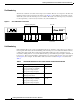
Installing 2T16S Network Processor Modules in the Cisco 4000 Series Table 1 2T16S Network Processor Module Configurations 2 High-Speed Serial Connectors 2 Low-Speed Serial Connectors Product Number Right Connector and Left Connector Port 0 and Port 1 Middle Connector Ports 2 to 9 Top Connector Ports 10 to 17 2T16S-RS232 Choice of EIA/TIA-232 DTE or DCE V.35 DTE or DCE X.
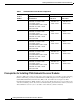
Installing 2T16S Network Processor Modules in the Cisco 4000 Series Software Compatibility Network processor modules must be supported by the appropriate level of system software. The minimum system software version for the 2T16S network processor module is as follows: • 2T16S-RS232 and 2T16S-V.35—Cisco IOS Release 11.2(3)P for synchronous and Cisco IOS Release 11.2(4)P for asynchronous operation • 2T16S-X.21—Cisco IOS Release 11.2(5)P • 2T16S-232V35 and 2T16S-232X21—Cisco IOS Release 11.
Installing 2T16S Network Processor Modules in the Cisco 4000 Series • Locate the room’s emergency power-off switch. Then, if an electrical accident occurs, you can quickly turn OFF the power. • Before working on the system, turn OFF the power and unplug the power cord.
Installing 2T16S Network Processor Modules in the Cisco 4000 Series Caution For safety, periodically check the resistance value of the antistatic strap, which should be between 1 and 10 megohm (Mohm).
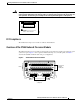
Installing 2T16S Network Processor Modules in the Cisco 4000 Series Slot Numbering The chassis contains slots for three network processor modules. These slots correspond to the three slot numbers printed on the front panel of the chassis. (See Figure 3.) Slot numbers represent the order in which the system scans the network processor modules. The location of network processor modules is not slot dependent; you can move any module to any other available slot.
Installing 2T16S Network Processor Modules in the Cisco 4000 Series If the second 2T16S module in Figure 2 was replaced by an Ethernet module, the unit addresses would be as listed in Table 3.
Installing 2T16S Network Processor Modules in the Cisco 4000 Series Warning Before releasing the safety latch, support the component tray from underneath, either on your work surface or with your hands, to prevent personal injury. (See Figure 4.
Installing 2T16S Network Processor Modules in the Cisco 4000 Series Warning Support the component tray from underneath, either on your work surface or with your hands, to prevent it from falling. (See the hand in Figure 5.) Figure 5 Component Tray Removal for Chassis without a Safety Latch Chassis shell Chassis release screw TX RX AUI LNK POL PORT-1 10BASE-T PORT-0 TX RX AUI LNK POL P0 P1 SERIAL P0 SERIAL INPUT 100-240VAC Rear of chassis Hand supporting component tray 50/60HZ 3.0-1.
Installing 2T16S Network Processor Modules in the Cisco 4000 Series Step 2 Grasp the network processor module handle and pull it straight up to lift the module out of its connector. (See Figure 6.) Step 3 Place the removed module on an ESD mat. Caution Do not wiggle the handle of the network processor module, and do not exert any side-to-side pressure because the handle might work loose and damage the network processor module.
Installing 2T16S Network Processor Modules in the Cisco 4000 Series Figure 7 Network Processor Module Components Module handles Male module connector (cutaway view) Female module connector on the motherboard Safety latch H1048a Chassis wall Module mounting screw Installing Network Processor Modules You can install up to three 2T16S network processor modules per chassis.
Installing 2T16S Network Processor Modules in the Cisco 4000 Series Aligning the 2T16S Network Processor Module with the Chassis H8761 Figure 8 Step 5 Make sure that the male connector on the network processor module is lined up side-to-side with the female connector on the motherboard, and then gently press point A shown in Figure 9.
Installing 2T16S Network Processor Modules in the Cisco 4000 Series Figure 10 Correct Installation of the Network Processor Module Incorrect installation showing connectors not firmly seated. H8760 Correct installation showing connectors firmly seated. Step 7 Replace the module mounting screw in its place on the end of the network processor module. (See Figure 6.) Step 8 Replace external rear mounting screws, if used, to attach the module to the rear of the chassis.
Installing 2T16S Network Processor Modules in the Cisco 4000 Series When you face the front of the chassis, the three LEDs (labeled OK) on the lower left correspond to the three network processor modules, if present. (See Figure 2.) When on, these LEDs indicate that the network processor modules are operational. The upper LEDs (labeled DATA) blink to indicate network activity on the respective interfaces.
Installing 2T16S Network Processor Modules in the Cisco 4000 Series High-Speed Serial Ports The two high-speed synchronous serial ports use two 60-pin D-type connectors to attach to the transition cable. Each port requires a serial adapter cable, which provides the interface between the high-speed serial port and the standard connectors that are commonly used for each electrical interface type.
Installing 2T16S Network Processor Modules in the Cisco 4000 Series The adapter cable also determines the electrical interface type and mode (DCE or DTE) of the port to which it is connected. Because the low-speed serial ports require special adapter cables, we recommend that you obtain serial interface cables from Cisco Systems (contact Customer Service at 800 553-6387, 408 526-7208, or cs-rep@cisco.com).
Installing 2T16S Network Processor Modules in the Cisco 4000 Series The data rate depends on the type of electrical interface used. EIA/TIA-232 only supports speeds up to 64 kbps; X.21, V.35, EIA/TIA-449, or EIA-530A support higher speeds. Note that EIA/TIA-449 or EIA-530A interfaces are only supported on the high-speed serial ports. When connecting serial devices, consider the adapter cables as an extension of the router for external connections.
Installing 2T16S Network Processor Modules in the Cisco 4000 Series High-Speed Cable Overview The router-end of the high-speed serial cable is a 60-pin D-sub connector, and the network end reflects the interface type and mode (see Figure 11 and Figure 12 for examples). The high-speed port supports the following DTE cables: CAB-232MT=, CAB-449MT=, CAB-V35MT=, CAB-X21MT=, or CAB-530MT=; the port supports the following DCE cables: CAB-232FC=, CAB-449FC=, CAB-V35FC=, or CAB-X21FC=.
Installing 2T16S Network Processor Modules in the Cisco 4000 Series Figure 14 EIA/TIA-449 Adapter Cable Connectors, Network End DCE H1344a DTE EIA-530 Connections EIA-530, which supports balanced transmission, provides the increased functionality, speed, and distance of EIA/TIA-449 on the smaller, DB-25 connector used for EIA/TIA-232.
Installing 2T16S Network Processor Modules in the Cisco 4000 Series X.21 Connections The X.21 interface uses a 15-pin connection for balanced circuits and is commonly used in the United Kingdom to connect public data networks. X.21 relocates some of the logic functions to the DTE and DCE interfaces and, as a result, requires fewer circuits and a smaller connector than EIA/TIA-232. The network end of the X.21 adapter cable is a standard DB-15 connector, as shown in Figure 17. X.
Installing 2T16S Network Processor Modules in the Cisco 4000 Series Cable Product Number Description Figure Reference CAB-OCT-X21-MT DTE mode—Molex LFH 200-pin connector and a DB-15-pin X.21 plug Figure 20 and Figure 17 CAB-OCT-X21-FC DTE mode—Molex LFH 200-pin connector and a DB-15-pin X.21 receptacle Figure 20 and Figure 17 Figure 18 Low-Speed EIA/TIA-232 Compact Serial Cable EIA/TIA-232 connectors Pin 161 Molex LFH 200-pin connector H7381 Pin 60 Pin 1 Pin 200 Figure 19 Low-Speed V.
Installing 2T16S Network Processor Modules in the Cisco 4000 Series Figure 20 Low-Speed X.21 Compact Serial Cable X.21 connectors Pin 161 Molex LFH 200-pin connector Pin 1 H7380 Pin 60 Pin 200 Installing the Cable Support Tray Because of the bulk of the low-speed serial cables, a cable support tray must be used in conjunction with the 2T16S network processor module. (See Figure 21.
Installing 2T16S Network Processor Modules in the Cisco 4000 Series Cable Support Tray Figure 22 Mounting Cable Support Tray on Chassis H7878 H7877 Figure 21 P0 IAL R SE P1 -1 RT PO TX RX I AUK LN L PO -0 -T SE RT PO BA 10 TX RX I AUK LN L PO P0 L RIA SE P1 Installing 2T16S Network Processor Modules in the Cisco 4000 Series 78-3277-03 27
Installing 2T16S Network Processor Modules in the Cisco 4000 Series Cable Support Tray Mounted on Chassis H7879 Figure 23 P0 L RIA SE P1 1 RT- PO TX RX I AUK LN L PO 0 RT- -T PO SE BA 10 TX RX I AUK LN L PO P0 IAL R SE P1 Attaching U-Shaped Cable Clamps to the Cable Support Tray Use the U-shaped cable clamps to route wires from the high-speed and low-speed ports on your 2T16S network processor modules.
Installing 2T16S Network Processor Modules in the Cisco 4000 Series Step 5 Attach the top bracket, notches down, over the serial port wires to the U clamp. The notches on the U-shaped clamp hold the top clamp in place automatically. Push the top clamp down far enough to hold the wires snugly in place. (See Figure 25.
Installing 2T16S Network Processor Modules in the Cisco 4000 Series Routing Serial Wires from the 2T16S Network Processor Module through the U Clamp H8750 Figure 25 Removing the U-Shaped Cable Support Clamp from the Cable Support Tray You can remove U-shaped cable support clamps or move them to another location on the cable support tray. To remove a U clamp, push up on the center rivet pin from under the cable support tray. (See Figure 26.
Installing 2T16S Network Processor Modules in the Cisco 4000 Series Bottom of Rivet on the Cable Support Tray H8751 Figure 26 Rivet pin Connecting Serial Cables to the Network Processor Module This section describes how to connect cables to the high-speed and low-speed serial connectors at the back of the router. It also describes the process of routing cables on the cable-support tray. Making High-Speed Serial Connections The two high-speed serial ports use 60-pin D-type connectors.
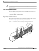
Installing 2T16S Network Processor Modules in the Cisco 4000 Series Figure 27 Making High-Speed Serial Connections to the 2T16S Network Processor Module 2T16S network processor module 17 16 1514 1312 1110 Router (rear view) 9 8 7 6 5 4 3 2 P1 SERIAL High-speed serial ports (2) AUX Modem or CSU/DSU H6442 Serial port 60-pin connector P0 EIA/TIA-449 port EIA/TIA-232, V.35, EIA/TIA-449, EIA-530, or X.
Installing 2T16S Network Processor Modules in the Cisco 4000 Series High-Speed Serial Cables Connected to the 2T16S Network Processor Module H7880 Figure 28 P0 L RIA SE P1 1 RT- PO TX RX I AUK LN L PO 0 RT- -T PO SE BA 10 TX RX I AUK LN L PO P0 L RIA SE P1 Making Low-Speed Serial Connections The 16 low-speed serial ports use two 200-pin D-type connectors.
Installing 2T16S Network Processor Modules in the Cisco 4000 Series Step 3 Attach the EIA/TIA-232, V.35, or X.21 end of the cable to the CSU/DSU or modem. (See Figure 29 on page 34.) Step 4 Repeat Steps 1 through 3 for each low-speed serial connection you are making. For cable routing, see Figure 30 through Figure 33 (page 35 through page 38). Step 5 If all your network connections are complete, proceed to the section “Connecting the Power Cord and Switching on the Router” on page 39.
Installing 2T16S Network Processor Modules in the Cisco 4000 Series Routing One Low-Speed Serial Cable on the Cable Support Tray H7881 Figure 30 P0 IAL R SE P1 1 RT- PO TX RX I AUK LN L PO 0 RT- -T PO SE BA 10 TX RX I AUK LN L PO P1 Installing 2T16S Network Processor Modules in the Cisco 4000 Series 78-3277-03 35
Installing 2T16S Network Processor Modules in the Cisco 4000 Series Routing Two Low-Speed Serial Cables on the Cable Support Tray H7882 Figure 31 P0 L RIA SE P1 1 RT- PO TX RX I AUK LN L PO 0 RT- -T PO SE BA 10 TX RX I AUK LN L PO P1 Installing 2T16S Network Processor Modules in the Cisco 4000 Series 36 78-3277-03
Installing 2T16S Network Processor Modules in the Cisco 4000 Series Routing Three Low-Speed Serial Cables on the Cable Support Tray H7883 Figure 32 P1 1 RT- PO TX RX I AUK LN L PO 0 RT- -T PO SE BA 10 TX RX I AUK LN L PO L RIA SE P1 Installing 2T16S Network Processor Modules in the Cisco 4000 Series 78-3277-03 37
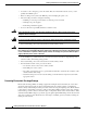
Installing 2T16S Network Processor Modules in the Cisco 4000 Series Routing Four Low-Speed Serial Cables on the Cable Support Tray H7884 Figure 33 P0 L RIA SE P1 1 RT- PO TX RX I AUK LN L PO 0 RT- -T PO SE BA 10 TX RX I AUK LN L PO P0 L RIA SE P1 Configuring Serial Connections The 2 high-speed serial ports and the 16 low-speed serial ports can be configured as DTE or DCE, depending on the transition cable used. The ports are numbered right to left, bottom to top. See Figure 34.
Installing 2T16S Network Processor Modules in the Cisco 4000 Series Figure 34 2T16S Network Processor Module 0-7 17 16 1514 1312 1110 Low-speed 200-pin serial ports LEDs 9 7 5 3 8 6 4 2 P1 SERIAL P0 H6412 0-7 High-speed 60-pin serial ports You must use a special serial transition cable to connect the Cisco 4000 series router to a modem, CSU/DSU, or other device. This cable, which is available from your customer service representative, is normally ordered with the system.
Installing 2T16S Network Processor Modules in the Cisco 4000 Series Figure 35 DC-Input Power Supply Connections Negative Ground Positive Terminal block cover On/off Terminal block H2552 Captive screw Grommet Terminal block cover Terminal block Grommet Configuring the 2T16S Network Processor Module Interface When you install a new network processor module or if you want to change the configuration of an existing interface, you must enter the configuration mode to configure the interfaces.
Installing 2T16S Network Processor Modules in the Cisco 4000 Series Note The configure command requires privileged-level access to the EXEC command interpreter, which usually requires a password. Contact your system administrator to obtain access if necessary. The following sections describe the commands for configuring an external clock signal for a DCE interface and for configuring a port for NRZI encoding or 16-bit cyclic redundancy check (CRC).
Installing 2T16S Network Processor Modules in the Cisco 4000 Series When a port is operating in DCE mode, the default operation is for the attached DTE device to return the clock signal (SCTE) to the DCE port. The DCE sends SCT and SCR clock signals to the DTE, and the DTE returns an SCTE clock signal to the DCE.
Installing 2T16S Network Processor Modules in the Cisco 4000 Series Step 2 Select the serial interface to configure: Router(config)# interface serial 2 Router(config-if)# The prompt changes again to show that you are in interface configuration mode. Note Step 3 The serial interface numbers for the low-speed ports can be 2 to 17 or 20 to 35 as previously described in Table 1.
Installing 2T16S Network Processor Modules in the Cisco 4000 Series Calculating CRCs on Cisco 4000 Series Serial Interfaces All Cisco 4000 series router serial interfaces support CRC-CCITT, a 16-bit CRC. CRC is an error-checking technique that uses a calculated numeric value to detect errors in transmitted data. The sender of a data frame divides the bits in the frame message by a predetermined number to calculate a remainder or frame check sequence (FCS).
Installing 2T16S Network Processor Modules in the Cisco 4000 Series The key to problem solving in this system is to try to isolate the problem to a specific subsystem. By comparing what the system is doing to what it should be doing, the task of isolating a problem is greatly simplified. When problem solving, consider the following subsystems of the router: • Power system—This subsystem includes the power supply and the wiring. • Cooling system—The fan should go on when power is applied.
Installing 2T16S Network Processor Modules in the Cisco 4000 Series Cisco Connection Online Cisco Connection Online (CCO) is Cisco Systems’ primary, real-time support channel. Maintenance customers and partners can self-register on CCO to obtain additional information and services. Available 24 hours a day, 7 days a week, CCO provides a wealth of standard and value-added services to Cisco’s customers and business partners.
Installing 2T16S Network Processor Modules in the Cisco 4000 Series Installing 2T16S Network Processor Modules in the Cisco 4000 Series 78-3277-03 47
Installing 2T16S Network Processor Modules in the Cisco 4000 Series This document is to be used in conjunction with the Cisco 4000 Series Installation Guide, the Cisco 4000 Hardware Installation and Maintenance, Cisco 4000 Series Hardware Installation and Maintenance, and the Regulatory Compliance and Safety Information documents that shipped with your router.