
Datasheet


Installing 2T16S Network Processor Modules in the Cisco 4000 Series
10
Installing 2T16S Network Processor Modules in the Cisco 4000 Series
78-3277-03
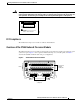
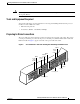
Slot Numbering
The chassis contains slots for three network processor modules. These slots correspond to the three slot
numbers printed on the front panel of the chassis. (See Figure 3.) Slot numbers represent the order in
which the system scans the network processor modules. The location of network processor modules is
not slot dependent; you can move any module to any other available slot.
Figure 3 Cisco 4000 Series—Front View
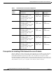
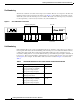
Unit Numbering
Unit numbering allows the system to distinguish between two interfaces of the same type. Looking at
the rear panel of the chassis, the unit numbering of the network processor modules increments from zero,
counting from right to left. The system assigns unit number addresses to these network processor
modules by starting with zero for each module interface type and numbering from right to left and from
bottom to top. The lowest unit number of that interface type is the module closest to the power supply.
(See Figure 2.) For example, the unit number addresses for the modules in Figure 2 are as listed in
Table 2.
Network activity LEDs
Run LED
H2427
2
DATA
OK
3
DATA
OK
1
DATA
OK
Health LEDs
Power LED
POWER
OK
SERIES
Table 2 Unit Number Addresses for Two 2T16S Modules and One Ethernet Module
Slot Interface Type Address
1 Low-speed serial port (top)
Low-speed serial port (middle)
High-speed serial port (left)
High-speed serial port (right)
10 to 17
2 to 9
1
0
2 Ethernet port (top)
Ethernet port (bottom)
1
0
3 Low-speed serial port (top)
Low-speed serial port (middle)
High-speed serial port (left)
High-speed serial port (right)
28 to 35
20 to 27
19
18