Infrastructure Protection on Cisco Catalyst 6500 and 4500 Series Switches A key element in an organization's overall security posture is the security of the network infrastructure. The network infrastructure is the foundation built with routers, switches, and other equipment that provide the fundamental network services that keep a network running. The infrastructure is often the target of denial of service (DoS) and other attacks that can directly or indirectly disrupt the network operation.
Configuring PACLs in Cisco IOS 13 Unicast MAC Address Filtering (MAC Address-Based Traffic Blocking) IP Permit Lists 15 Access-Class 15 Locking Down Unused Ports 16 14 Spanning Tree Protocol Security 17 Disabling Auto-Negotiated Trunking 18 Per VLAN Spanning Tree (PVST) 19 BPDU Guard 20 STP Root Guard 23 Routing Protocol Security 24 Neighbor Authentication 24 Route Filtering 25 TTL Security Check 26 Catalyst Integrated Security 27 Port Security 27 Configuring Port Security in Catalyst OS 28 Configuring Po
CoPP Technology Overview 53 CoPP on Supervisors 720 and 32 (Catalyst 6500) 54 Configuring CoPP on Supervisors 720 and 32 (Catalyst 6500) 55 Catalyst 6500 Series Switch CoPP Considerations and Restrictions CoPP on Catalyst 4500 57 Configuring CoPP on Catalyst 4500 Series Switches 59 Catalyst 4500 Series Switch CoPP Considerations and Restrictions Defining CoPP Traffic Classes 61 Recommended CoPP Deployment Methodology 62 Sample CoPP Configuration 64 Additional Catalyst 6500 Infrastructure Protection Features
Layer 2 Port Security 84 Layer 2 PDU 84 Layer 2 Protocol Tunneling Multicast IGMP 85 85 Integrated Deployment Guidelines 86 Deploying Basic Device Hardening Tools and Techniques Spanning Tree Protocol Security 87 Deploying Routing Protocol Security 88 Deploying Catalyst Integrated Security 89 Catalyst 6500 Hardware Rate Limiters and CoPP 90 Additional References 86 91 Unneeded Services 91 Unneeded Services in Cisco IOS and Catalyst OS 92 Cisco Discovery Protocol (CDP) 92 ICMP Redirects 93 ICMP Unreacha
SSH in Cisco IOS SNMP Access 108 108 Other Security Services 109 TCP Intercept 109 Private VLANs 109 802.
directly connected to its destination subnet, and if the switch is configured to do so, that packet is exploded as a broadcast on the destination subnet. In this way, a single directed broadcast packet can reach multiple destinations, and can be used by programs such as smurf, to amplify the effects of an attack. A smurf attack, named after its exploit program, is a DoS attack that uses spoofed broadcast ping messages to flood a target system.
• Warning banners—Login banners should be used not only to dissuade possible attackers but also because in some jurisdictions they are required by law. Banners must give notice that any unauthorized use of the system is unlawful, and can be subject to civil or criminal penalties. Also important, banners should not reveal any platform or configuration-related information.
Router ACL Router ACLs, also known as Cisco IOS ACLs, are the standard and extended IP ACLs available on Cisco IOS Software. These ACLs are applied to Layer 3 interfaces and to VLAN interfaces, and affect only routed traffic. In addition, router ACLs can be applied in a specific inbound or outbound direction. As with IOS routers, standard IP access lists are based on source addresses, while extended IP ACLs can be based on source and destination addresses, and optionally on protocol type information.
In Catalyst 4500 Series switches, VACLs are supported only on systems running Cisco IOS. In this platform, VACLs can be configured for IP and MAC-layer traffic. In the case of IP, the VACLs can be configured to map Layer 3 address information. All other non-IP protocols can be controlled with MAC-based ACLs, which use MAC address and Ethertype information to match packets. Catalyst 6500 Series switches support VACLs on both Catalyst OS and Cisco IOS.
Console> (enable) set security acl ip IPACL1 permit host 172.20.53.4 0.0.0.0 IPACL1 editbuffer modified. Use 'commit' command to apply changes. Console> (enable) Console> (enable) commit security acl all ACL commit in progress. ACL IPACL1 is committed to hardware. Console> (enable) Console> (enable) set security acl map IPACL1 10 ACL IPACL1 mapped to vlan 10 Console> (enable) This example shows a MAC-based VACL called MACACL1 and that permits all traffic from 8-2-3-4-7-A.
Switch(config)# access-list 101 permit udp any any Switch(config)# ip access-list extended igmp-match Switch(config-ext-nacl)# permit igmp any any Switch(config)# ip access-list extended tcp-match Switch(config-ext-nacl)# permit tcp any any Switch(config-ext-nacl)# exit ! !--- Create VLAN map and define actions per map instance Switch(config)# vlan access-map drop-ip-default 10 Switch(config-access-map)# match ip address 101 Switch(config-access-map)# action forward Switch(config-access-map)# exit Switch(co
Port ACL (PACL) Port ACLs (PACLs) are IP based and MAC based access control lists applied to Layer 2 physical ports on a switch. PACLs are available on Catalyst 6500 Series switches running Catalyst OS and Catalyst 4500 Series switches running Cisco IOS. Note PACLs are available only on Supervisor Engine 720 with PFC3A/PFC3B/PFC3BXL and Supervisor Engine 32 with PFC3B. Only input PACLs are supported on Catalyst 6500 Series switches equipped with those supervisor engines.
Table 1 Interaction Between PACLs, VACLs, and Router ACLs ACL Type PACL Mode Prefer Port Prefer VLAN Merge Input router ACL PACL applied Input router ACL applied PACL, Input router ACL (merged) applied in order (ingress) VACL PACL applied VACL applied PACL, VACL (merged) applied in order (ingress) VACL + Input router ACL PACL applied VACL + Input router ACL PACL, VACL, Input router ACL applied (merged) applied in order (ingress) Configuring PACLs in Catalyst OS To configure PACLs in Catalyst O
Step 3 Apply the previously defined ACLs to the desired Layer 2 port using the access-group interface configuration command: Switch(config-if)# {ip | mac access-group {name | number| in | out} In the following example an IP ACL and a MAC ACL are defined and applied to interface FastEthernet 6/1. The IP ACL, called simple-ip-acl, is configured to permit all TCP traffic and implicitly deny all other IP traffic. The MAC ACL, simple-mac-acl, is configured to permit source host 000.000.
IP Permit Lists The IP permit list is an available feature in Catalyst OS and supported on Catalyst 6500 and 4500 Series switches. An IP permit list is an access-list that prevents inbound Telnet, SNMP, and SSH access to the switch from unauthorized source IP addresses. All other TCP/IP services (such as IP traceroute and IP ping) continue to work normally when you enable the IP permit list.
In the following example, Telnet and SSH access to VTYs 0 to 4 is restricted to host 172.16.1.1 only. Switch(config)# access-list 10 permit 172.16.1.1 Switch(config)# line vty 0-4 Switch(config-line)# access-class 10 in For more information on how to configure an access-class, refer to the following URL: http://www.cisco.com/univercd/cc/td/doc/product/software/ios122/122cgcr/fipras _r/1rfip1.
http://www.cisco.com/univercd/cc/td/doc/product/lan/cat6000/sw_8_5/cmd_ref/set_v.htm#wp1058935 For more information on the set vlan command for the Catalyst 4500, refer to the following URL: http://www.cisco.com/univercd/cc/td/doc/product/lan/cat4000/8_3/command/set_s_z.htm#wp1052100 By default, in Cisco IOS all interfaces are disabled on Catalyst 6500 Series switches, and enabled on Catalyst 4500 Series switches.
A newer version of STP, called Rapid-STP (RSTP), is defined in IEEE 802.1w. RSTP works similarly to STP, but provides better convergence after a failure of a switch, switch port, or a LAN. RSTP significantly reduces the time to reconfigure the active topology of the network when changes to the physical topology or its configuration parameters occur. RSTP supersedes STP specified in 802.1D, but remains compatible with STP.
This example shows how to disable auto-negotiation on port 2 on module 1: Console> (enable)#set trunk 1/2 off Port(s) 1/2 trunk mode set to off. Console> (enable) For more information on the set trunk command on the Catalyst 6500, refer to the following URL: http://www.cisco.com/univercd/cc/td/doc/product/lan/cat6000/sw_8_5/cmd_ref/setsy _tr.htm#wp1170006 For more information on the set trunk command on the Catalyst 4500, refer to the following URL: http://www.cisco.
is not supported on non-Cisco devices. Rapid-Per-VLAN-Spanning Tree (Rapid-PVST+) is another version of PVST that provides faster convergence of the spanning tree by using Rapid Spanning Tree Protocol (RSTP) with the existing configuration for PVST+. PVST+ and Rapid-PVST+ are available on Catalyst 6500 and 4500 Series switches for both Catalyst OS and Cisco IOS.
spanning tree. When enabled on a port, BPDU guard shutdowns the port as soon as a BPDU is received in that port. In this way, BPDU guard helps prevent unauthorized access and the illegal injection of forged BPDUs. BPDU guard requires STP PortFast to be configured on the port first. STP PortFast causes a Layer 2 LAN port configured as an access port to enter the forwarding state immediately, bypassing the listening and learning states.
To enable BPDU guard on an interface of a system running Cisco IOS, use the spanning-tree bpduguard command. You must first enable PortFast on the port.
STP Root Guard STP Root Guard is an available feature on Catalyst 6500 and 4500 Series switches running Catalyst OS and Cisco IOS software that enforces the placement of the root bridge. STP root guard is a feature that is enabled on selected ports to prevent surrounding switches from becoming the root switch. The root guard feature forces a port to become a designated port so that no switch on the other end of the link can become a root switch.
For more information on the spanning-tree guard root command on the Catalyst 4500, refer to the following URL: http://www.cisco.com/univercd/cc/td/doc/product/lan/cat4000/12_2_31s/cmdref/snmp _vtp.htm#wp1031770 Routing Protocol Security Routing is one of the most important parts of an infrastructure to keep a network running and, as such, it is absolutely critical to take the necessary measures to secure it.
• Open Shortest Path First (OSPF) • Routing Information Protocol (RIP) version 2 The configuration commands and steps to enable neighbor authentication vary depending on the routing protocol. To find complete configuration information for specific routing protocols, refer to the Cisco IOS IP Protocols Configuration Guide at the following URL: http://www.cisco.com/en/US/products/sw/iosswrel/ps1835/products_configuration_guide _book09186a0080087fa9.
TTL Security Check Based on the Generalized TTL Security Mechanism (GTSM, RFC 3682), the TTL security check is a security feature that protects BGP peers from multi-hop attacks. This feature allows the configuration of a minimum acceptable TTL value for the packets exchanged between two eBGP peers. When enabled, both peering routers transmit all their traffic to each other with a TTL of 255.
Catalyst Integrated Security The first sections of this document presented a collection of basic tools and techniques for infrastructure protection. This section introduces a set of advanced security features that are designed to take advantage of the unique Catalyst 6500 and 4500 hardware architectures, making these switching platforms more resilient to attacks, and thereby providing enhanced protection for the infrastructure.
Note • Restrict—Drops packets with unknown source addresses until you remove a sufficient number of secure MAC addresses to drop below the maximum value and causes the SecurityViolation counter to increment. • Shutdown—Puts the interface into the error-disabled state immediately and sends an SNMP trap notification.
For more information on how to configure Port Security on Catalyst 6500 running Catalyst OS, refer to the following URL: http://www.cisco.com/univercd/cc/td/doc/product/lan/cat6000/sw_8_5/confg_gd/sec_port.htm For more information on how to configure Port Security on Catalyst 4500 running Catalyst OS, refer to the following URL: http://www.cisco.com/univercd/cc/td/doc/product/lan/cat4000/8_3/configur/sec_port.
MAC Address Monitoring MAC address monitoring is a feature present on Catalyst 6500 Series switches running Catalyst OS and Cisco IOS software. This feature helps mitigate MAC flooding and other CAM overflow attacks by limiting the total number of MAC addresses learned by the switch on per-port or per-VLAN basis. With MAC Address Monitoring, a maximum threshold for the total number of MAC addresses can be configured and enforced on a per-port and/or per-VLAN basis.
VLANs. If you specify the shutdown keyword, and the configuration is a port/VLAN combination, the violation action error disables the port. If you specify the warning keyword, the system displays a system message when the high threshold is exceeded: Console> (enable) set cam monitor high-threshold value [action {no-learn | shutdown | warning}] {mod/port | {mod/port vlan} | vlan} Step 5 Optionally, specify the polling interval for monitoring using the set cam monitor interval command.
To configure MAC address monitoring on a Catalyst 6500 switch running Cisco IOS, perform the following steps: Step 1 The first step in the configuration is to enable MAC address monitoring globally using the mac-address-table limit command. To change the default global configuration, use the following command options. The maximum keyword specifies the maximum number of MAC entries per VLAN per EARL allowed, valid values are from 5 to 32000 MAC-address entries.
Conceptually, Catalyst 6500 and 4500 Series switches implement the traffic storm feature in a similar manner. However, there are some implementation differences. Traffic storms can consist of unicast, multicast, or broadcast packets. Traffic storm control in Catalyst 6500 Series switches can monitor and limit unicast, multicast, and broadcast packet storms while in Catalyst 4500, storm control can monitor and limit multicast and broadcast packet storms only.
Broadcast suppression is disabled by default. To configure broadcast suppression on the Catalyst 6500 running Catalyst OS, use the set port broadcast command.
if you need to control the volume of BPDUs or other Layer 2 PDUs. Note that the hardware-based rate limiters must be used cautiously, they control traffic globally and can also have potential side effects on the Layer 2 connectivity. Refer to Hardware-Based Rate Limiters on Supervisors 32 and 720, page 72 for more information. Traffic storm control is disabled by default.
Note Storm control is supported in hardware on all ports on the WS-X4516 supervisor engine. In contrast, the supervisor engines WS-X4515, WS-X4014, and WS-X4013+ support storm control in hardware on non-blocking gigabit ports and in software on all other ports, implying that the counters for these interfaces are approximate and computed. Multicast storm control is only supported on the WS-X4516 supervisor engine.
Unicast and Multicast Flood Blocking As part of the normal operation of a switch, each time a packet with an unknown destination MAC address is received, the packet is forwarded to all ports on the switch, with the exception of the port from which the packet was received.
Catalyst 6500 Unknown Unicast Flood Blocking (Cisco IOS) In Catalyst 6500 Series switches running Cisco IOS software, the unicast flood blocking feature is called Unknown Unicast Flood Blocking (UUFB). By default, all the Layer 2 ports on the switch are configured to allow unicast flooding. To block unicast flooding on Layer 2 ports, perform the following steps: Step 1 Enter global configuration mode and select the interface to configure.
Switch(config-if)# switchport block unicast Switch(config-if)# end For more information on port unicast and multicast flood blocking on the Catalyst 4500 running Cisco IOS, refer to the following URL: http://www.cisco.com/univercd/cc/td/doc/product/lan/cat4000/12_2_31s/conf/uniflood.htm DHCP Snooping DHCP snooping is a security feature capable of intercepting DHCP messages crossing a switch and blocking bogus DHCP offers.
packet. MAC address verification is available on Catalyst 6500 Series switches and is enabled by default in both, Cisco IOS and Catalyst OS. In Catalyst OS this feature is called the MAC-Address Matching option. This feature is not supported on Catalyst 4500. Catalyst 6500 Series switches have the capacity to insert Option-82 information as DHCP packets are received.
Step 6 Optionally, enable the MAC-Address Matching option (in case it has been disabled). Use the set dhcp-snooping match-mac enable command: Console> (enable) set dhcp-snooping match-mac enable Step 7 Optionally, enable DHCP snooping host-tracking information Option-82 feature when the DHCP clients and servers do not reside in the same subnet or network, and the switch seats between them.
Additionally in Cisco IOS, DHCP Snooping implements a software-based rate limiting function that controls the number of DHCP packets a port can receive. This rate limiting function is disabled by default but can be enabled by configuration. DHCP snooping puts ports where the rate limit is exceeded into the error-disabled state. Cisco recommends not configuring the rate limit to more than 100 packets per second on an untrusted port.
Step 6 Optionally, for Catalyst 6500, enable DHCP Option-82 data insertion when the DHCP clients and servers do not reside in the same subnet or network, and when the switch seats between them. Use the ip dhcp snooping information option command: Router(config)# ip dhcp snooping information option Step 7 Optionally, for Catalyst 4500, when used as an aggregation switch, configure the switch to accept DHCP requests with Option-82 information from any snooping untrusted port.
• IP source guard cannot coexist with PACLs. • IP source guard is not supported on EtherChannel-enabled ports, and EtherChannel is not supported on IP source guard-enabled ports. • VLAN-based ACL features, such as static ARP inspection, are disabled when you enable IP source guard. Note We recommend that you enable high availability when using dynamic ARP inspection (DAI), DHCP snooping, and IP source guard.
IP Source Guard enabled on port(s) 3/1. Console> (enable) set port dhcp-snooping 1/2 trust enable Port(s) 1/2 state set to trusted for DHCP Snooping. Console> (enable) set security acl ip dhcpsnoop permit dhcp-snooping Successfully configured DHCP Snooping for ACL dhcpsnoop. Use the 'commit' command to save changes. Console> (enable) set security acl ip dhcpsnoop permit ip any any dhcpsnoop editbuffer modified. Use the 'commit' command to apply changes.
Step 5 Optionally, configure a static IP binding on the port. Use the ip verify source vlan dhcp-snooping port-security command: Switch(config)# ip source binding mac-address vlan vlan-id ip-address interface interface-name This example shows how to enable per-Layer 2-port IP source guard on VLANs 10 through 20: Switch# configure terminal Enter configuration commands, one per line. End with CNTL/Z.
Similarly to DHCP snooping, DAI associates a trust state with each interface on the system. Packets arriving on trusted interfaces bypass all DAI validation checks, while those arriving on untrusted interfaces go through the DAI validation process. In a typical network configuration for DAI, all ports connected to host ports are configured as untrusted, while all ports connected to switches are configured as trusted.
In this example, dynamic ARP inspection is configured on VLAN 100, while port 2/2 is set as trust: Console> (enable) set security acl arp-inspection dynamic enable 100 Dynamic ARP Inspection is enabled for vlan(s) 100. Console> (enable) set port arp-inspection 2/2 trust enable Port(s) 2/2 state set to trusted for ARP Inspection. To configure ARP Inspection for non-DHCP systems, perform the following steps: Step 1 Configure the ARP traffic-inspection ACL with the valid static MAC-IP binding entries.
To optionally configure DAI to drop the packets with invalid MAC or IP addresses use the set security acl arp-inspection address-validation command. The following MAC addresses are considered invalid 00-00-00-00-00-00, multicast MAC addresses (the 48th bit is set), and ff-ff-ff-ff-ff-ff (this is a special-case multicast MAC address). The following IP addresses are considered invalid 0.0.0.0, 255.255.255.255, and class D (multicast) IP addresses.
For more information on Dynamic ARP Inspection on Catalyst 6500 Series switches running Catalyst OS, refer to the following URL: http://www.cisco.com/univercd/cc/td/doc/product/lan/cat6000/sw_8_5/confg_gd/acc_list.htm Dynamic ARP Inspection (DAI) in Cisco IOS (Catalyst 6500 and Catalyst 4500) As with Catalyst OS, in Cisco IOS, DAI can be configured to drop ARP packets containing MAC addresses in their bodies that do not match the addresses specified in the Ethernet headers.
Switch(config)# arp access-list acl-name Switch(config-arp)# permit ip host sender-ip mac host sender-mac [log] Switch(config-arp)# exit Step 2 Apply the ARP ACL to the VLAN. By default, no defined ARP ACLs are applied to any VLAN.Use the ip arp inspection filter command: Switch(config)# ip arp inspection filter arp-acl-name vlan vlan-range [static] Step 3 Configure the port trust state. By default, all interfaces are untrusted. Use the ip arp inspection trust command.
Step 2 Optionally, enable error recovery from the dynamic ARP inspection error-disable state. By default, every time the rate of incoming ARP packets exceeds the configured limit, the switch places the port in the error-disabled state. Enabling error-disable recovery allows ports to automatically emerge from this state after a specified timeout period.
CoPP Technology Overview Control Plane Policing (CoPP) protects Catalyst 6500 and 4500 switches by allowing the definition and enforcement of QoS policies that regulate the traffic processed by the main switch CPU (route or switch processor). With CoPP, these QoS policies are configured to permit, block, or rate limit the packets handled by the main CPU.
CoPP on Supervisors 720 and 32 (Catalyst 6500) CoPP is supported on Catalyst 6500 Series switches and Cisco 7600 Series Routers with Supervisors 720 and 32 running Cisco IOS software. This section describes the implementation details of CoPP on Supervisors 720 and 32. In the Catalyst 6500 Series switches, CoPP takes advantage of the processing power present on line-cards by implementing a distributed CoPP model.
Note CoPP is not enforced in hardware unless MLS QoS is globally enabled using the mls qos command. Another important characteristic of CoPP in Supervisors 720 and 32 is that it does not support the definition of non-IP traffic classes, with the exception of the class-default. Class-default is a default class for all remaining traffic destined to the RP that does not match any other class.
Step 4 After the traffic is classified, you apply a policy action to each class, indicating whether to permit all packets, to drop all packets, or to drop packets crossing a specified rate limit for that particular class. To apply these policy actions use the policy-map command, which has the following syntax: Router((config-pmap)# policy-map service_policy_name The policy-map command defines the policy map name and enables a configuration mode for defining the policy.
• Currently, multicast packets are handled only by the software-based CoPP at the RP level. However, there are CPU rate limiters available that can rate limit multicast packets to the CPU in hardware. These CPU rate limiters include the Multicast FIB-miss rate limiter and the Multicast Partial-SC rate limiter. These CPU rate limiters can be used in combination with ACLs and software CoPP to provide protection against multicast and DoS attacks. • CoPP is not supported in hardware for broadcast packets.
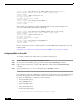
Figure 5 Catalyst 4500 CoPP 16 CPU Queues Switch CPU Control and CPU Bound Traffic Ingress Control Plane Forwarding ASICs DataTraffic Backplane Linecard 190962 Linecard Contrary to the Catalyst 6500, Catalyst 4500's CoPP supports the definition of non-IP traffic classes in addition to IP traffic classes. With this, instead of using the default class for handling all non-IP traffic, you can define separate policies for non-IP traffic.
Table 2 Catalyst 4500 System Predefined ACLs system-cpp-igmp IP Protocol = IGMP, IPDA matches 224.0.0.0/3 system-cpp-pim IP Protocol = PIM, IPDA matches 224.0.0.0/24 system-cpp-all-systems-on-subnet IPDA = 224.0.0.1 system-cpp-all-routers-on-subnet IPDA = 224.0.0.2 system-cpp-ripv2 IPDA = 224.0.0.9 system-cpp-ip-mcast-linklocal IP DA = 224.0.0.
Step 5 After the traffic is classified, you apply a policy action to each class, indicating whether to permit all packets, to drop all packets, or to drop packets crossing a specified rate limit for that particular class. To apply these policy actions use the policy-map command, which has the following syntax: Switch(config)# policy-map system-cpp-policy The policy-map command defines the policy map name and enables a configuration mode for defining the policy.
Defining CoPP Traffic Classes Developing a CoPP policy starts with the classification of the control plane traffic. To that end, the control plane traffic needs to be first identified and separated into different class-maps. The Catalyst 4500 Series switches provides the system-cpp macro which automatically generates a collection of class-maps for common Layer 3 and Layer 2 control plane traffic.
7. Critical Applications This class defines application traffic that is crucial to a specific network. The protocols that might be included in this class include generic routing encapsulation (GRE), Hot Standby Router Protocol (HSRP), Virtual Router Redundancy Protocol (VRRP), Dynamic Host Configuration Protocol (DHCP), IPSec, and multicast traffic. 8. Undesirable This explicitly identifies unwanted or malicious traffic that should be dropped and denied access to the RP.
Configure each ACL to permit all known protocols in its class that require access to the RP. At this point, each ACL entry should have both source and destination addresses set to any. In addition, the ACL for the default class should be configured with a single entry: permit ip any any. This will match traffic not explicitly permitted by entries in the other ACLs. After the ACLs have been configured, create a class-map for each class defined in Step 1, including one for the default class.
At this point, you might decide to remove the class-map and ACL used for the classification of default traffic. If so, you should also replace the previously defined policy for the default class by the class-default policy. Sample CoPP Configuration The following example shows how to develop a CoPP policy and how to apply it in order to protect the control plane of a Catalyst 6500 Series switch. In this example, the control plane traffic is classified based on relative importance and traffic type.
! Allow the router to receive NTP packets from a known clock source permit udp host 10.2.2.3 host 10.1.1.1 eq ntp ! ! The File Management class is for file transfer traffic required ! for software and configuration maintenance, in this example, TFTP ! and FTP is classified in this class ip access-list extended coppacl-filemanagement remark CoPP file management traffic class ! Allow router initiated FTP (active and passive) permit tcp 10.2.1.0 0.0.0.255 eq 21 host 10.1.1.1 gt 1023 established permit tcp 10.
Table 3 Note Sample CoPP Policy File management 6,000,000 Transmit Drop Monitoring 900,000 Transmit Drop Critical applications 900,000 Transmit Drop Undesirable 32,000 Drop Drop Default 500,000 Transmit Drop The rates defined in Table 3 were successfully tested on a Cisco Catalyst 6500 Series switch with Supervisor 720. It is important to note that the values presented here are solely for illustration purposes, every environment will have different baselines.
! ! Monitoring traffic is limited to a rate of 900,000 bps, if traffic exceeds ! that rate it is dropped class coppclass-monitoring police cir 900000 bc 9000 be 9000 conform-action transmit exceed-action drop ! ! Critical-app traffic is limited to a rate of 900,000 bps, if traffic ! exceeds that rate it is dropped class coppclass-critical-app police cir 900000 bc 9000 be 9000 conform-action transmit exceed-action drop ! ! This policy drops all traffic categorized as undesirable, regardless ! of rate.
Note uRPF requires that Cisco Express Forwarding (CEF) is enabled. An important characteristic of uRPF is that it enables this functionality with minimal operational overhead and in a scalable, timely manner. In addition, uRPF introduces minimal performance impact to a device. It is thus a highly attractive alternative to traditional ACLs. The Catalyst 6500 Supervisor 2, Supervisor 32 and Supervisor 720 support uRPF in hardware. There are currently two uRPF modes available: strict mode and loose mode.
• Interface-group—The PFC3 performs the Unicast PRF check in hardware for single-path and two-path prefixes. The PFC3 also performs the Unicast PRF check for up to four additional interfaces per prefix through user-configured multipath Unicast PRF check interface groups. Unicast RPF check is disabled for packets coming from other multipath prefixes that have three or more reverse-path interfaces (these packets always pass the Unicast PRF check).
Router(config)# mls rate-limit unicast acl output 50000 50 Because both ingress and egress limiters share the same rate-limiter register, when one of them is changed, both values change to the last configured value. In the following example, the output rate is changed to 40000 pps: Router(config)# mls rate-limit unicast acl output 40000 50 For more information on the mls rate-limit unicast acl command, refer to the following URL: http://www.cisco.com/univercd/cc/td/doc/product/lan/cat6000/122sx/cmdref/m1.
For more information on the mls rate-limit unicast acl vacl-log command, refer to the following URL: http://www.cisco.com/univercd/cc/td/doc/product/lan/cat6000/122sx/cmdref/m1.htm#wp1719874 Layer 3 Security Features (Unicast Only) Some security features are processed by first being sent to the MSFC. For these security features, you need to rate limit the number of these packets being sent to the MSFC to reduce any potential overloading.
This example shows how to define the routing-protocol packet policing: Router(config)# mls qos protocol bgp police 32000 For more information on the mls qos protocol command, refer to the following URL: http://www.cisco.com/univercd/cc/td/doc/product/lan/cat6000/122sx/cmdref/m1.
Note The hardware-based rate limiters don't provide the same level of granularity as CoPP but can be used in cases where CoPP cannot classify particular types of traffic (for example, packets that fail the MTU check, and packets with IP options). We recommend that you use CoPP and hardware-based rate limiters together. However, be aware that some hardware-based rate limiters override the CoPP policy.
This example shows how to rate limit the uRPF check failure packets sent to the MSFC to 100000 pps with a burst of 100 packets: Router(config)# mls rate-limit unicast ip rpf-failure 100000 100 Note The ICMP unreachable no route, ICMP unreachable ACL drop, IP errors, and IP RPF failure rate-limiters share a single rate-limiter register. If any of these limiters are enabled, all of the limiters in this group will share the same value and sometimes the same state (for example, ON/ON/ON).
ICMP Redirects (Unicast Only) The ICMP-redirect rate limiter allows you to rate limit ICMP traffic. For example, when a host sends packets through a nonoptimal switch, the MSFC sends ICMP-redirect messages to the host to correct its sending path. If this traffic occurs continuously, and is not rate limited, the MSFC will continuously generate ICMP-redirect messages. This rate limiter is disabled by default.
Router(config)# mls rate-limit unicast cef receive pps [packets-in-burst] This example shows how to rate limit the traffic to 25000 pps with a burst of 60: Router(config)# mls rate-limit unicast cef receive 25000 60 Note Do not enable the FIB receive rate limiter if you are using CoPP. The FIB receive rate limiter overrides the CoPP policies. For more information on the mls rate-limit unicast cef receive command, refer to the following URL: http://www.cisco.
Layer 3 Security Features (Unicast Only) Some security features are processed by first being sent to the MSFC. For these security features, you need to rate limit the number of these packets being sent to the MSFC to reduce any potential overloading. The security features include authentication proxy (auth-proxy), IPSec, and inspection. Do not enable this rate limiter unless you are planning to use any of these features. Authentication proxy is used to authenticate inbound or outbound users or both.
MTU Failure (Unicast and Multicast) Similar to the TTL failure rate limiter, the rate limiter for MTU failures is supported for both unicast and multicast traffic. Packets that fail an MTU check are sent to the MSFC CPU. This might cause the MSFC to be overwhelmed. This rate limiter is disabled by default. To enable and set the MTU Failure rate limiter, use the mls rate-limit all mtu-failure command.
This rate limiter is disabled by default. To enable and set the Layer 2 protocol tunneling rate limiter, use the mls rate-limit layer2 l2pt command. Router(config)# mls rate-limit layer2 l2pt pps [packets-in-burst] This example shows how to rate limit Layer 2 protocol tunneling packets to 10000 pps with a burst of 10 packets: Router(config)# mls rate-limit layer2 l2pt 10000 10 For more information on the mls rate-limit layer2 l2pt command, refer to the following URL: http://www.cisco.
to the MSFC3 for forwarding and replication, which might otherwise increase CPU utilization. This rate limiter is enabled by default with a limit of 100000pps, and a burst of 100 packets. To enable and set the multicast partially switched flows rate limiter, use the mls rate-limit multicast ipv4 partial command. Router(config)# mls rate-limit multicast ipv4 partial pps [packets-in-burst] The multicast directly connected rate limiter limits the multicast packets from directly connected sources.
• Static sharing of a rate limiter with another pre-configured rate limiter—When there are not enough adjacency-based rate limiters available, you can share a rate limiter with a pre-configured rate limiter (target rate limiter).
http://www.cisco.com/univercd/cc/td/doc/product/lan/cat6000/122sx/cmdref/m1.htm#wp1502440 Configuring Hardware-Based Rate Limiters in Catalyst OS The following list shows the hardware-based rate limiters available on Catalyst 6500 Series switches running Catalyst OS: • ACL Bridge Packets, page 82 • The ACL Feature (ARP Inspection, DHCP Snooping, 802.
This rate limiter is enabled by default with a rate of 1000 pps. To set the ACL feature rate limiter, use the set security acl feature ratelimit command. Console> (enable) set security acl feature ratelimit rate A rate value of 0 disables this rate limiter. We strongly recommend, however, that you do not disable rate limiting because traffic that is redirected by various security features might flood the supervisor engine and diminish system performance.
http://www.cisco.com/univercd/cc/td/doc/product/lan/cat6000/sw_8_5/cmd_ref/setsn _su.htm#wp1099527 Layer 2 Port Security The Layer 2 Port Security rate limiter limits the rate at which packets are processed on ports with port security enabled. Note Hardware-based rate limiters are supported on Catalyst 6500 Series switches that are configured with a Distributed Forwarding Card 3A (DFC3A) or the Policy Feature Card 3 (PFC3) only. The Catalyst 6500 Series switch cannot be in truncated mode.
Console>(enable) set rate-limit l2pdu rate 1000 Layer 2 rate limiter for PDU rate set to 1000. Console>(enable) For more information on the set rate-limit l2pdu command, refer to the following URL: http://www.cisco.com/univercd/cc/td/doc/product/lan/cat6000/sw_8_5/cmd_ref/set_po _r.htm#wp1597259 Layer 2 Protocol Tunneling This rate limiter limits Layer 2 protocol tunneling packets, which include control PDUs, CDP, STP, and VTP packets destined for the route processor.
For more information on the set multicast ratelimit command, refer to the following URL: http://www.cisco.com/univercd/cc/td/doc/product/lan/cat6000/sw_8_5/cmd_ref/set_m _pi.htm#wp1119887 Integrated Deployment Guidelines The tools and techniques described in this document are very valuable for protecting Cisco Catalyst 6500 and 4500 Series switches from direct attacks and the negative effects of accidental misconfiguration.
• Deploying banners • Implementing role-based access • Securing web-based GUI Access • Use secure access protocols (SSH) instead of clear text protocols (telnet) • Controlling SNMP access These practices are described in Access Control, page 98. Layer 2 and Layer 3 Access Control Lists (ACLs) are also essential security features because they can help shield the infrastructure from DoS, source address spoofing, and other attacks.
occurs in one VLAN, the effects are contained in that VLAN, shielding the rest of the network. The Catalyst switches implement several versions of PVST (such as PVST+ and Rapid-PVST+). It should be noted that some of these versions are Cisco proprietary, and they should not be used in multi-vendor environments. Another good practice is to enable BPDU guard on all ports connecting to non-switching devices, such as workstations and servers. Non-switching devices are not supposed to participate in STP.
available, MD5 authentication should be used instead because it does not reveal any key information. MD5 authentication helps prevent the insertion of bogus routers into the routing domain, prevents the injection of forged routing updates, and in addition it ensures the integrity of routing updates. IS-IS, EIGRP and RIPv2 offer the additional function of key chains. A key chain is a series of keys with lifetimes, and which are used in sequence. This decreases the likelihood of keys being compromised.
Traffic storm control (traffic suppression) is a feature that can be configured on selected ports to control packet storms. We recommend that you configure traffic storm control on ports where traffic storms can enter the network, typically the access ports. When deploying traffic control. it is important to understand the platform limitations.
While deploying hardware-based rate limiters there are some important considerations that should be taken into account: • CoPP is preferable over the FIB (CEF) Receive rate limiter. Use CoPP rather than this rate limiter and do not use both mechanisms in conjunction. • Do not use the IP Sec features rate limiter unless you are using authentication proxy, IPSec, or inspection. • Do not use the VACL log rate limiter unless VACL Log is configured.
Note Before disabling a service, first verify that the service is not needed. This section describes how to disable some services that might not be needed.
For more information about CDP in Catalyst OS, refer to the following URL: http://www.cisco.com/univercd/cc/td/doc/product/lan/cat6000/sw_8_5/cmd_ref/ses _sete.htm#wp1026797 For more information about CDP in IOS, refer to the following URL: http://www.cisco.com/en/US/partner/tech/tk962/technologies_tech_note09186a00801aa000.
• On systems running Cisco IOS, ICMP unreachables can be disabled per interface by using the no ip unreachables interface configuration command, as shown in the following example: Router(config-if)# no ip unreachables For more information about the Catalyst OS set ip unreachable disable command, refer to the following URL: http://www.cisco.com/univercd/cc/td/doc/product/lan/cat6000/sw_8_5/cmd_ref/set_f _l.
Directed Broadcast An IP directed broadcast packet is an IP packet whose destination address is a valid broadcast address for an IP subnet. When a directed broadcast packet reaches a router that is directly connected to its destination subnet, and if the router is configured to do so, that packet is “exploded” as a broadcast on the destination subnet. By default, earlier releases of Cisco IOS software handle directed broadcasts this way.
http://www.cisco.com/univercd/cc/td/doc/product/software/ios123/123cgcr/fun_r/cfr _1g03.htm#wp1031545 For more information about AutoInstall, refer to the following URL: http://www.cisco.com/en/US/products/sw/iosswrel/ps1835/products_configuration_guide _chapter09186a00800ca735.
For more information about the ip proxy-arp command, refer to the following URL: http://www.cisco.com/univercd/cc/td/doc/product/software/ios123/123cgcr/ipras_r/ip1 _i2g.htm#wp1081466 TCP and UDP Small Servers TCP and UDP small servers are daemons that typically run on Unix systems and that were designed for diagnostic purposes. Cisco IOS software also provides an implementation of UDP and TCP small servers that enables echo, chargen, daytime and discard services.
Access Control There are more access mechanisms to a switch than many administrators realize, from console to a variety of remote sessions based on protocols like Telnet, rlogin and SSH. Most of these mechanisms are not enabled by default, but others like console are. In every case it is critical to control who accesses the device. Anyone who gains access to a switch can obtain critical information about the network, reconfigure the device, and even take the device out of service.
Retype new password: Password changed. Console> (enable) For more information about the set password command, refer to the following URL: http://www.cisco.com/univercd/cc/td/doc/product/lan/cat6000/sw_8_5/cmd_ref/set_m _pi.htm#wp1025848 The set enablepass Command In switches running Catalyst OS, privileged access to the CLI is controlled with a local enable password, which by default is not configured. Use the set enablepass command to configure a CLI enable password.
http://www.cisco.com/univercd/cc/td/doc/product/lan/cat6000/sw_8_5/cmd_ref/ses _sete.htm#wp1052196 The set authentication enable Command By default, privilege access to switches running Catalyst OS is controlled with the local enable password. The set authentication enable command can be used to enable TACACS+, RADIUS, or Kerberos as alternative authentication methods for enable (privilege) access.
For more information about the service password-encryption command, refer to the following URL: http://www.cisco.com/univercd/cc/td/doc/product/software/ios123/123cgcr/secur_r/sec _r1g.htm#wp1070450 The enable secret Command The enable secret global configuration command is used to set the password that grants privileged administrative access to the Cisco IOS software system. By default, no enable secret password is enabled, and as a general best practice, one should always be set.
Router(config)# security authentication failure rate 3 log This configuration causes access to the router to be locked for a period of 15 seconds after three unsuccessful login attempts, disabling the dictionary method of attack. In addition to locking access to the router, this configuration causes a log message to be generated after three unsuccessful login attempts, warning the administrator of the unsuccessful login attempts.
Console> (enable) set authentication login local disable telnet local login authentication set to disable for telnet session. Console> (enable) Console> (enable) set ip permit 172.16.0.0 255.255.0.0 ssh 172.16.0.0 with mask 255.255.0.0 added to telnet permit list. Console> (enable) Console> (enable) set ip permit enable ssh SSH permit list enabled. Console> (enable) Console> (enable) set logout 3 Sessions will be automatically logged out after 3 minutes of idle time.
The following configuration illustrates the best practices just described. In this configuration, access for VTY 4 is restricted to only SSH connections coming from the IP address 10.0.0.1. The line timeout is set to 2 minutes and 30 seconds, and tcp keepalives are enabled. service tcp-keepalives-in access-list 10 permit host 10.0.0.1 line vty 4 transport input ssh access-class 10 in exec-timeout 2 30 Cisco IOS Login Enhancements Cisco IOS software Release 12.
Legal notification requirements are complex, and vary in each jurisdiction and situation. Even within jurisdictions, legal opinions vary, and this issue should be discussed with your own legal counsel. In cooperation with counsel, you should consider which of the following information should be put into your banner: • A notice that the system is to be logged in to or used only by specifically authorized personnel, and perhaps information about who can authorize use.
Console> (enable) set tacacs server 170.1.2.20 primary 170.1.2.20 added to TACACS server table as primary server. Console> (enable) set tacacs key MyKey The tacacs key has been set to MyKey. Console> (enable) set ip http server enable HTTP server is enabled. Console> (enable) set authentication login tacacs enable http primary tacacs login authentication set to enable for HTTP sessions as primary authentification method.
Step 3 Deploy HTTP ACLs to allow access only from trusted hosts or networks. In IOS this can be done using the ip http access-class global configuration command. The following example shows how access to the HTTP server is configured to be allowed from a single host (10.0.0.1) only. Router(config)# ip http access-class 10 Router(config)# access-list 10 permit host 10.0.0.1 For more information on the http access-class command, refer to the following URL: http://www.cisco.
Console> set ip permit 172.18.124.0 255.255.255.0 172.18.124.0 with mask 255.255.255.0 added to IP permit list. !--- Step 3: Turn SSH on. Console> (enable) set ip permit enable ssh SSH permit list enabled. For more information about SSH configuration on Catalyst OS, refer to the following URL: http://www.cisco.com/univercd/cc/td/doc/product/lan/cat6000/sw_8_5/confg _gd/connect.
SNMP versions 1 and 2c are weak in security. In these earlier versions of SNMP, access to MIB objects is primarily controlled by the use of community strings, but neither version provides authentication or encryption. Without authentication it is possible for unauthorized users to execute SNMP transactions, and even masquerade legitimate users.
• Community—Community ports communicate among themselves and with their promiscuous ports. These interfaces are separated at Layer 2 from all other interfaces in other communities or isolated ports within their PVLAN. For more information about PVLANS on Catalyst 6500 Series switches running Cisco IOS, refer to the following URL: http://www.cisco.com/univercd/cc/td/doc/product/lan/cat6000/122sx/swcg/pvlans.
Firewall Services Module (FWSM) The Firewall Services module (FWSM) is a high-speed, integrated firewall module for Cisco Catalyst 6500 switches and Cisco 7600 Series routers, and provides the fastest firewall data rates in the industry: 5-Gbps throughput, 100,000 CPS, and 1M concurrent connections. Up to four FWSMs can be installed in a single chassis providing scalability to 20 Gbps per chassis.
complete DDoS protection system. By constantly monitoring for, and detecting the start of, potential DDoS attacks, the Cisco Traffic Anomaly Detector Services module enables the activation of intelligent mitigation by the Cisco Anomaly Guard. The combined solution provides a scalable, flexible, and cost-effective method to help ensure that business integrity is always preserved, even while under attack.