
Leaflet

9
OL-11615-01
In Catalyst 4500 Series switches, VACLs are supported only on systems running Cisco IOS. In this
platform, VACLs can be configured for IP and MAC-layer traffic. In the case of IP, the VACLs can be
configured to map Layer 3 address information. All other non-IP protocols can be controlled with
MAC-based ACLs, which use MAC address and Ethertype information to match packets.
Catalyst 6500 Series switches support VACLs on both Catalyst OS and Cisco IOS. In addition, VACLs
support IP and IPX-based VACLs, and MAC-based ACLs. IP and IPX traffic can be controlled by
mapping Layer 3 address information, while other non-IP traffic can be filtered based on MAC address
and Ethertype information using MAC-based ACLs.
Catalyst 6500 Series switches require the following hardware in order to support VACLs:
• Supervisor Engine 1 with a PFC
• Supervisor Engine 2 with a PFC2
• Supervisor Engine 720 with a PFC3A/PFC3B/PFC3BXL
• Supervisor Engine 32 with a PFC3B
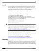
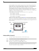
VACLs can be used in conjunction with router ACLs. Figure 1 shows the logical relationship between
VACLs and router ACLs. When used together with router ACLs, a VACL is first applied to incoming
packets on the corresponding ingress VLAN. If the packet is Layer 3 forwarded and is permitted by the
VACL, it is filtered by the Cisco IOS ACL on the same VLAN. The same process happens in reverse in
the egress direction.
Figure 1 Logical Relationships Between VACLs and Router ACLs
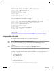
Configuring VACLs in Catalyst OS
To configure a VACL in Catalyst OS software, perform the following steps:
Step 1 Create VACL and add entries using the set security acl command.
Step 2 Commit the VACL to NVRAM using the commit command.
Step 3 Map VACL to a VLAN using the set security acl map command.
This example shows an IP-based VACL called IPACL1 and that allows traffic from source address
172.20.53.4. This VACL is then mapped to VLAN 10:
190958
Host A
VLAN 20VLAN 10
Host B
VACL
Routing Function
Switching Function
VACL
Input
Router
ACL
Output
Router
ACL