CLP-9001/9301 User’s Manual
FCC COMPLIANCE STATEMENT FOR AMERICAN USERS This equipment has been tested and found to comply with the limits for a Class A digital device, pursuant to Part 15 of the FCC Rules. These limits are designed to provide reasonable protection against harmful interference when the equipment is operated in a commercial environment.
EMI COMPLIANCE STATEMENT FOR CANADIAN USERS This Class A digital apparatus complies with Canadian ICES-003. This equipment generates and uses radio frequency energy and if not installed and used properly, that is, in strict accordance with the manufacturer's instructions, may cause interference to radio and television reception.
Important Safety Instructions 1. Read all of these instructions and save them for later reference. 2. Follow all warnings and instructions marked on the product. 3. Unplug this product from the wall outlet before cleaning. Do not use liquid or aerosol cleaners. Use a damp cloth for cleaning. 4. Do not use this product near water. 5. Do not place this product on an unstable cart, stand or table. The product may fall, causing serious damage to the product. 6.
Notice 1. Before use, be sure to read this manual. And keep it handy for reference when needed. 2. The contents of this manual may change without prior notice. 3. Reproduction, transfer, or transmission of the contents of this manual without prior consent is strictly prohibited. 4. We are not liable for any damage resulting from the use of the information contained herein, regardless of errors, omissions, or misprints. 5.
Introduction Thank you for purchasing a new Citizen CLP series label printer. This manual is designed to help you quickly understand the basic operations of this printer. Design features This printer is designed to accurately print bar codes and various character fonts on media such as tags and labels at high speeds. Both direct thermal and thermal transfer printing is possible.
Table of Contents FCC Compliance Statement for American Users ..............................i Compliance Statement for European Users ......................................i EMI Compliance Statement for Canadian Users...............................ii Important Safety Instructions .............................................................iii Notice.................................................................................................iv Trademark Acknowledgement ..................................
Chapter 6 Configuring Your Printer Using the Menus ...............37 6.1 The Group Menu .....................................................................37 6.2 Page Setup Menu ...................................................................38 6.3 System Setup Menu................................................................39 6.4 After Print Menu ......................................................................41 6.5 Interface Setup Menu........................................................
− viii −
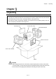
Chapter 1 Unpacking Chapter 1 Unpacking First open the carton and take out the accessory box and the printer front cover, then lift the printer main body out of the carton, holding the bottom of the printer firmly. Also keep the carton and packing materials as the printer must be packed properly with the carton and packing materials for future shipment.
Chapter 1 Unpacking 1.1 Checking items inside the accessory box First, you should check that all of the following items are inside the accessory box. If any are missing, please contact your supplier.
Chapter 2 Safety Precautions Chapter 2 Safety Precautions This chapter describes safety precautions when using the printer. Please read and understand the precautions in this chapter before using the printer. Safety signs The various safety signs included in this manual and pasted on the printer are intended to inform you of the correct and safe handling of this printer and protect against personal injury and property damage.
Chapter 2 Safety Precautions WARNING Avoid unsafe places Avoid unsafe places such as the top of a shaky desk, an uneven surface or any area subject to vibration. Failure to observe this precaution may cause the printer to fall or turn over, resulting in injury. Dot not put water-filled containers nearby Do not put containers filled with water or chemical liquids such as vases and cups near the printer.
Chapter 2 Safety Precautions Power cord Do not damage, break or modify the power cord. Putting heavy objects on the power cord or heating or pulling it may cause damages, leading to fire and electrical shock. If the power cord is damaged (e.g., the core is exposed or the wire broken), contact our service personnel. Continued use without corrective action may result in fire or electrical shock. When using, do not bend, twist, or pull the power cord.
Chapter 2 Safety Precautions CAUTION Avoid high-humidity areas Do not put the printer in areas with high-humidity or heavy condensation. If moisture has condensed on the printer, turn off the power switch immediately and leave the printer for a while until the moisture dries up. Using the printer when damp may result in electrical shock. Carrying Before carrying the printer, be sure to remove the plug from the outlet and the connecting cable to the outer equipment.
Chapter 2 Safety Precautions Opening/closing the right side cover When opening/closing the right side cover, be careful not to catch your fingers between the cover and chassis. When opening, open the cover all the way until it stops at the hinges, and then release your hand. When closing, close the cover fully and then release your hand. Printhead The printhead remains at a high temperature immediately after printing.
Chapter 2 Safety Precautions Installation precautions After reading and understanding the safety signs, install the printer, observing the following precautions: Avoid dust Dust can stop the printer from cleanly printing a document. It can also cause breakdowns and shorten the printer life.
Chapter 3 Names and Functions of Printer Parts Chapter 3 Names and Functions of Printer Parts This chapter describes the names and functions of each part of the printer. 3.1 Printer main body 1 Opening/closing and detachment of the front cover To open the front cover, catch hold of the right edge of the front cover with your fingers and open it in the direction as shown with arrow.
Chapter 3 Names and Functions of Printer Parts 1 2 3 4 5 6 7 8 9 Front cover Right side cover Control panel Printhead lever Printhead Printhead pressure knob Platen Right side cover grip Paper guide roller 8 11 2 10 Paper guide roller release lever 11 Paper sensors 12 Paper sensor adjust-knob R 13 Paper guide (rotation and horizontal movement) 14 15 16 17 18 T 16 Paper roll shaft Cushion roller Ribbon bobbin holders Paper holder Printhead pressure gauge 6 14 15 1 17 3 A 18 7 4 5 B 10 CAUTIO
Chapter 3 Names and Functions of Printer Parts Rear and side covers 25 19 Media viewing window 26 23 20 AC main power input port 21 Power switch 22 Parallel interface connector (or optional IEEE1284ECP or Ethernet interface connector) 22 23 RS-232C serial interface connector 21 24 (not used) 25 Optional USB interface slot plate 26 (not used) 20 19 24 − 11 −
Chapter 3 Names and Functions of Printer Parts 3.2 Control panel The control panel consists of an LCD displaying two lines of eight characters, two LEDs and six control keys. Two functions are assigned to each key except the MODE key. CLP-9001 POWER READY MODE REPEAT STOP FEED UP MENU DOWN FUNCTION PAUSE EXIT SELECT Indications LCD (Display) Shows the current printer status by a message on the display. POWER LED Lights up when the printer power is turned on.
Chapter 3 Names and Functions of Printer Parts Control keys On the control panel legend, in Ready mode, the text written ABOVE each key shows the key’s function. In Menu mode, the text written BELOW each key shows the key’s function. MODE key When the MODE key is pressed, the printer is placed into the Ready mode. When the MODE key is pressed again, the printer is placed into the Menu mode. Each time the MODE key is pressed, the printer toggles between the Ready mode and Menu mode.
Chapter 3 Names and Functions of Printer Parts MODE key Printer enters the Menu mode, and the ‘∗ Page Setup’ menu is shown on the LCD (Display). (See P31) Key functions in the Menu mode MENU key Selects the next Group Menu or Menu Item. (See P31 − 33) UP key • Selects the next Group Menu or Menu Item. (See P31 − 33) • Selects the next Value of the Menu Item. (See P31 − 33) DOWN key • Selects the previous Group Menu or Menu Item. (See P31 − 33) • Selects the previous Value of the Menu Item.
Chapter 4 Media (Paper) and Ribbon − 15 −
Chapter 4 Media (Paper) and Ribbon Chapter 4 Media (Paper) and Ribbon This chapter describes all of the types of media available for this printer and how to load the media and ribbon. Unless otherwise specified, the term ‘media,’ ‘paper,’ ‘page,’ ‘labels’ or ‘tags’ is referring to any media that is being printed using the printer. 4.1 Types of media We recommend that you should use a genuine Citizen paper or its equivalent.
Chapter 4 Media (Paper) and Ribbon ♦ Center-punched hole tag Holes (2.5mm diameter) are perforated lengthwise along the central line of the tag. ♦ Black mark tag Black marks are printed on the back of the tag at the center or on the right side in the direction of feed. ♦ Corner-with-a-radius cut tag The cuts on the edge of this tag are deeper than the cuts on center-hole tag.
Chapter 4 Media (Paper) and Ribbon Label Media with adhesive material on the back are referred to as labels. Labels are peeled off the liner piece by piece and stuck to a product or item. ♦ Labels with inter-label gap There are gaps between labels. ♦ Black mark label Black marks are printed on the back of the label line on the central line or right side in the direction of feed.
Chapter 4 Media (Paper) and Ribbon 4.2 Paper size Minimum value mm (in) Maximum value mm (in) A Label width 19 (0.748) 115.00 (4.53) B Liner width 19 (0.748) 115.00 (4.53) C Label left edge position 0 D Label paper gap length 2 (0.079) 1016 (40) E Label length 6.5 (0.256)* 1016 (40) F Label pitch 6.5 (0.256) 1016 (40) G Liner thickness 0.06 (0.0025) 0.089 (0.0035) H Paper total thickness 0.14 (0.0055) 0.25 (0.01) I Notch right end position 3.75 (0.148) 11 (0.
Chapter 4 Media (Paper) and Ribbon 4.3 Loading the paper The out-wound roll of paper is the standard, although inward-wound media can also be used. See Page 23 for details. The paper core diameters for the roll of paper are 1, 3, or 4 inches. The standard core sizes are 1 and 3 inches.
Chapter 4 Media (Paper) and Ribbon 3. Move the blue printhead lever towards the back of the printer to lift the printhead block. Push the blue paper guide roller release lever to lift the paper guide roller, and lower the paper guide. Paper guide Paper guide roller release lever Printhead lever 4. Turn the blue paper holder knob counterclockwise, and remove the paper holder from the shaft.
Chapter 4 Media (Paper) and Ribbon 5. To load the roll of paper, first insert the paper core adaptors (3-inch) into the paper core (see SUGGESTION below), where they must be positioned properly, and put those onto the paper roll shaft, pushing the roll of paper to the deepest side, then attach the paper holder to the paper roll shaft.
Chapter 4 Media (Paper) and Ribbon 7. Let the edge of the roll of paper nearer to the control panel butt against the fan-shaped metal paper guide (on the deepest side) and turn the paper holder knob clockwise to lock the paper holder. Paper holder knob 8. Slide the blue paper guide to the edge of the roll of paper in the direction of feed and turn it upwards. Paper guide 9.
Chapter 4 Media (Paper) and Ribbon 10. Close the right side cover and the front cover. Loading the paper is now completed. CAUTION When the inward-wound roll of paper is used, first put the roll of paper onto the paper roll shaft so that it can be wound clockwise as shown blow, then pull the end of the roll of paper through the printer as before. Inward-wound CAUTION The maximum outer diameter of the inward-wound roll of paper is 250 mm (9.84 in).
Chapter 4 Media (Paper) and Ribbon 4.4 Loading the ribbon We recommend that you should use a genuine Citizen ribbon or its equivalent. The ribbon (with paper core) is loaded into the printer using the two ribbon bobbins supplied. The ribbon passes from the source ribbon core (unused) to the destination core of used ribbon. 1. Open the front cover by pulling the right hand side of the cover towards you. 2.
Chapter 4 Media (Paper) and Ribbon 4. Insert the bobbins into the source ribbon and destination paper cores respectively. 5. Fit the destination paper core with the bobbin on the left side ribbon shaft holder and click into position. 6. Feed the ribbon bobbin a certain length and set it on the right side ribbon shaft holder and click into position. 7. Pass the ribbon through the lower side of the printhead block onto the destination ribbon core.
Chapter 4 Media (Paper) and Ribbon 9. Close the right side cover and then close the front cover, allowing the magnetic catch to firmly hold the front cover. The ribbon is now loaded. NOTE The following procedure may help you load the ribbon more easily. First insert the bobbins into the source and destination ribbon cores, affix the adhesive tape at the end of the ribbon and then wind the ribbon around the bobbin until the tape is hidden.
Chapter 4 Media (Paper) and Ribbon 4.5 Printhead pressure adjustments The paper width for this printer is 19-115 mm (0.75-4.53 in). When a narrow width of paper or thick media is used, the printhead pressure across the print area is not even so poor print quality etc may occur. Before making adjustments, the paper must be loaded and the printhead block be lowered and locked. If the ribbon is loaded, the front bobbin should be removed and laid down in front of the printer.
Chapter 4 Media (Paper) and Ribbon 4.6 Paper sensor adjustments Using the paper sensor adjust-knob, adjustments to the paper sensor can be made to suit the kind of media that is being used. Before making adjustments, the paper must be loaded and the pinch roller be lowered. The two holes in the sensor arm correspond to the two different sensor positions, i.e., a hole ‘R’ for the reflective sensor and a hole ‘T’ for the transparent sensor.
Chapter 5 Power ON And Using The Control Panel Chapter 5 Power ON and Using the Control Panel After loading the paper and ribbon, connect the power cord and turn your printer on. 5.1 Connecting to a power outlet First plug the power cord into the AC power input on the back of the printer, then plug the other end of the power cord into the AC power outlet. CAUTION The specifications of the power cord may vary, depending on the rules of the destination.
Chapter 5 Power ON And Using The Control Panel 5.2 Turning the printer ON Turn ON the power switch. • Press “|” for ON. • Press “O” to turn off the printer. Once the power is turned ON, the following initial messages are displayed on the screen for about three seconds. Power ON Firmware version is displayed CF000100 DD/MM/YY System Starting The printer tests the printhead for damage Checking Head Failed XXX.
Chapter 5 Power ON And Using The Control Panel 5.3 Ready Mode and Menu Mode This section describes the operation flow of the Ready mode and Menu mode. This printer can be easily operated using the six keys on the control panel. Ready mode READY Receive data from host computer. READY ****** STOP REPEAT FEED PAUSE Perform function: • Stop printing • Repeat last label • Feed to TOF • Pause printing Return to ready mode after 5 sec of no more data. ****** = ‘Parallel’, ‘RS232C’, etc.
Chapter 5 Power ON And Using The Control Panel Ready mode The printer is in Ready mode after power is switched on and the self-test is performed. READY The LCD (Display) shows “READY” and the READY LED is lit. In this state, you can perform the paper feed, printing stop/restart etc using the keys on the control panel.
Chapter 5 Power ON And Using The Control Panel 5.5 Changing Menu Values With a Menu Item displayed on the LCD (such as Print Speed, Darkness or Baud Rate), pressing the key allows you to adjust or select the Value of the Menu Item. The and keys are used to increase or decrease a Value, such as the print speed or printing position.
Chapter 5 Power ON And Using The Control Panel Select the Print Darkness Menu Item. to bring up the Print Darkness function. • Press Print Darkness Show the Print Darkness current value. • Press to bring up the current Print Darkness value. Darkness 10 Change the setting to ″15″ • Press and hold • Press to increase the Value from ″10″ to ″15″ Darkness 15 to save the new value and printer returns to the Menu Item. When is pressed, the display goes back to ‘∗ Page Setup.
Chapter 5 Power ON And Using The Control Panel 5.7 Producing a Test or Configuration Print When the Test Mode is selected from the Group Menu, test and configuration prints, head element check and Hex Dump mode can be selected. The two test print patterns and two configuration printouts are available. Example: producing a test pattern print Press the key to display the Group Menu display. * Page Setup Select the ‘∗ Test Mode’ menu from the Group Menu • Press the key to move the display to ‘∗ Test Mode.
Chapter 5 Power ON And Using The Control Panel 5.8 Turning the printer OFF Do not turn the printer OFF suddenly. If the printer is printing, press the or key and wait for the printer to stop printing before turning the power switch OFF.
Chapter 5 Power ON And Using The Control Panel − 37 −
− 38 −
Chapter 6 Configuring Your Printer Using The Menus Chapter 6 Configuring Your Printer Using the Menus This chapter explains all the possible menu options for configuring the barcode printer. Refer to Chapter 5 for information on the operation of the menus system and which keys perform which actions. 6.1 The Group Menu The printer has two modes of operation: Ready mode and Menu mode. To switch between the modes, key.
Chapter 6 Configuring Your Printer Using The Menus 6.2 Page Setup Menu The Page Setup Menu allows the setting of items such as print speed, print darkness, direct or thermal transfer printing and horizontal and vertical position adjustments. Key * Page Setup Range Printing Speed Speed 02 IPS Speed 08 IPS Speed 06 IPS Print Darkness Darkness 00 Darkness 10 Darkness 30 Ribbon Torque Torque Torque Torque 1 4 Print Method Method DT/TT Method DT/TT * * This changes to 12 IPS for CLP-9001.
Chapter 6 Configuring Your Printer Using The Menus 6.3 System Setup Menu The System Setup Menu provides access to configure the hardware settings within the printer such as the type of media sensor used and the threshold for gap detection, metric or imperial (inches) selection, print resolution and time and date setting, if a clock module is installed. It also allows for user access to the control panel and settings to be locked out to avoid inadvertent changes.
Chapter 6 Configuring Your Printer Using The Menus Metric mode Inch mode MaxMedia Length Length 1.00IN Length 10.00IN Time Setting Time 00:15 Time 01:15 Date Setting Date 01/01/00 Settings Lock Lock On/Off Lock On/Off Keyboard Lock Lock On/Off Lock On/Off SOH-Cmd Ignore Ignore Yes/No Ignore Yes/No Control Code Code STD/ALT Code STD/ALT Language Select Cmd Set DMI Cmd Set DM4 Length 50.00IN Time 01:15 MENU Date 31/01/00 − 40 − Month 31/01/00 Cmd Set DPP Length Length 25.
Chapter 6 Configuring Your Printer Using The Menus 6.4 After Print Menu The After Print Menu allows you to configure what the printer does once the label has been printed, including whether the printer feeds to the tear position after a batch of labels, whether the printer cuts the labels and what type of cutter or peeler is installed.
Chapter 6 Configuring Your Printer Using The Menus 6.5 Interface Setup Menu The Interface Setup Menu configures the baud rate, parity, data length, protocols and stop bits for the standard serial interface. It also allows for the configuration of the optional network interface, including IP address, subnet mask and gateway addresses. The following menu flow chart is basically prepared for CLP-9301 but the different values between CLP-9301 and CLP-9001 are also shown as needed.
Chapter 6 Configuring Your Printer Using The Menus 6.6 Permanently Saving Settings Menu Settings made within the menu system of the printer are saved in standard memory. When the printer is switched off, these settings will be lost unless they are save to the non-volatile memory inside the printer. The Permanently Saving Settings Menu has just one option.
Chapter 6 Configuring Your Printer Using The Menus 6.8 Menu Mode Description Group Menu * Page Setup * System Setup Menu Item Printing Speed Default CLP-9301: 06 IPS CLP-9001: 06 IPS Range CLP-9301: 02 − 08 IPS CLP-9001: 02 − 12 IPS Description Set print speed. Print Darkness 10 00 − 30* Adjust print darkness. * This changes to 00 − 20 for DPP or DM4 language selected. Print Method TT DT / Direct Thermal TT / Thermal Transfer Set printing method. Ribbon Torque 4 1−5 Set ribbon torque.
Chapter 6 Configuring Your Printer Using The Menus Group Menu Menu Item * System Setup Metric/Inch Print Res. DPI (Print Res. DPmm) Default Inch CLP-9301: 300 CLP-9001: 200 CLP-9301: 300DPI (12 DPmm) 150DPI (6 DPmm) CLP-9001: 200DPI (8 DPmm) 100DPI (4 DPmm) AutoCal Mode MaxMedia Length Range Inch mm 10.00in 254.0mm 1.00 − 50.00in 25.4 − 1270.0mm Description Set basic unit of measurement to millimeters or inches. Set print resolution. Values in parentheses are in metric system.
Chapter 6 Configuring Your Printer Using The Menus Group Menu * After Print Menu Item Function Select Default Off Range Off Tear PeelWait Cut Description Select function mode and set the default media position after printing. (STX+fnnn command regards the position as zero point.) Off: Function mode is set to OFF. Tear: Enable tear mode. PeelWait: Enable peeler mode. (“PeelWait” is shown when the optional device is installed.) Cut: Enable cutter mode.
Chapter 6 Configuring Your Printer Using The Menus Group Menu * After Print * Interface * Save Settings Menu Item Cutter Type Default Standard Range Standard HeavyDty Description Select cutter type. (“Cutter Type” is shown when the optional device is installed.) Cutter Action Backfeed Backfeed Through Set media feed direction. (“Cutter Action” is shown when peeler unit is installed.) Backfeed: Always back feed media to top-of form after cutting operation.
Chapter 6 Configuring Your Printer Using The Menus Group Menu * Test Mode Menu Item Print Pattern Default Range Current setting Current setting Machine Info Pattern Slanting Pattern Sample Description Choose and execute a test print. The test pattern or configuration print can only be produced when there is no print job is in buffer. Head Check Check for faulty printhead elements. Factory Default Return to factory default setting values.
Chapter 6 Configuring Your Printer Using The Menus − 49 −
Chapter 7 Troubleshooting Chapter 7 Troubleshooting When an error occurs, an error message is displayed on the LCD panel. This chapter describes corrective actions to be taken when error message is received or problems or difficulties are experienced. 7.1 Items to check in case of trouble If problems or difficulties are experienced during the operation of the printer, please check the following table to try and resolve your problem. Symptom The LCD stays blank when the printer power is turned ON.
Chapter 7 Troubleshooting Symptom Text is not printed cleanly. Check Remedy 1. Is the paper and ribbon loaded properly? 2. Is the print density too dark or faint? Print position changes. 1. Load the paper and ribbon properly. 2. Set the proper print density via the menu or control software. 3. Is the platen dirty or deformed? 3. If the platen is dirty, remove the dirt using ethyl alcohol. If the platen is deformed, contact our service personnel for replacement. 4.
Chapter 7 Troubleshooting 7.2 Error messages and corrective actions The printer will be placed in error status and an error message will be displayed on the LCD (Display) if the printer has not been prepared properly for printing or printer setup conditions are not correct. Check error messages and take corrective actions to clear error. If a message other than the following is displayed, please contact our service personnel.
Chapter 7 Troubleshooting − 52 −
Chapter 8 Maintenance Chapter 8 Maintenance Since this printer uses a thermal head and a carbon ink ribbon、thermal paper dust etc may adhere to the printhead or other related parts. In this case, printing errors or failure of the printhead may occur. If paper dust or ribbon material adheres to the printhead, irregular printer movements, paper jams or poor print quality may occur. Therefore, be sure to clean the printhead, platen and paper path periodically.
Chapter 8 Maintenance 8.2 Cleaning method Remove dirt, paper dust, adhesive materials for labels etc upon completion of printing.
Chapter 9 Specifications Chapter 9 Specifications 9.1 General specifications Item CLP-9001 CLP-9301 Printing method Thermal Transfer/Direct Thermal Printhead resolution 203 DPI (8 dots/mm) approx 300 DPI (12 dots/mm) approx Maximum print width 104 mm (4.1 in) 105.7 mm (4.16 in) Print length 6.5 mm − 1,016 mm (0.25 − 40 in) 6.5 mm − 762 mm (0.25 in − 30 in) Print speed 2 − 12 IPS* 2 − 8 IPS Media Max. media roll diameter: 250 mm (9.
Chapter 9 Specifications 9.2 Interfaces 1 Serial interface Specifications Transfer method: Start stop synchronous dual communication system Signal level: RS-232C Baud rate: 2400, 4800, 9600, 14400, 19200, 38400, 57600, 115200 bps Data bits: 7 or 8 Start bits: 1 Stop bits: 1 or 2 Parity: Even, odd, or none Connector: D-SUB 25PIN 17LE-13250-27(D41)(DDK) or its equivalent XON/XOFF protocol XON code output requirements: • Communication is enabled after power is turned ON.
Chapter 9 Specifications DTR protocol DTR signal “Ready (High)” level requirements: The following must be satisfied: • Printer is on line. • Receive buffer has more than 1K bytes available. Note: When receive buffer has less than 128 bytes available, DTR signal becomes “Busy (Low)” level and this “Busy (Low) level is kept until receive buffer has at least 1K bytes available. DTR signal “Busy (Low)” level requirements: The following must be satisfied: • Printer is in error.
Chapter 9 Specifications 2 Parallel interface Specifications Transfer method: 8-bit parallel (compatibility mode) Synchronous: Strobe pulse Handshaking: ACKNLG and BUSY signals Signal level: TTL Printer side: 36-pin non-phenol type Pin assignment Pin No.
Chapter 9 Specifications 9.3 Printable area The accurate print position is illustrated below. Maximum media width: 115.0mm (4.53”) *Default print width for CLP-9301: 104.0mm (4.10”) 2.5mm (0.1”) Margin Printable area (0,0) Paper guide Direction of paper feed − 59 − *101.
Chapter 9 Specifications 9.4 Adjustable sensor The required detection position can be set with the adjustable sensor. The adjustable sensor mechanism is illustrated below. Paper guide 115mm (4.5”): maximum paper width 0.8mm (0.03”) for Transparent sensor 57.8mm (2.27”): sensor adjustable range 3.95mm (0.16”) for Reflective sensor 57.8mm (2.27”): sensor adjustable range Media Sensor Setup Guide Setup Voltage Voltage Level Black Mark Reflective No Mark area 2.1V 1.7V or less No Gap area 1.
Chapter 9 Specifications 9.5 Auto-Cutter (optional) Two kinds of auto-cutter are available: standard and heavy-duty versions. 1 Standard auto-cutter specifications Cutting method: Guillotine cutter Maximum thickness of cut paper : 0.15 mm (0.006 in) Minimum length of cut paper: 25.4 mm (1 in) (For details, see the user’s manual of the standard auto-cutter.) Guillotine cutter Sensor Printhead 26.2mm (1.03”) 87mm (3.
Chapter 9 Specifications 9.6 Peeler (optional) Peeler specifications Paper width: Maximum diameter of paper roll: Minimum inner diameter of paper roll: Maximum label length: Minimum label length: Maximum paper thickness: Maximum liner thickness: 115 mm (4.53 in) 203 mm (8 in) 76 mm (3 in) 120 mm (4.72 in) 25.4 mm (1 in) 0.17 mm (0.067 in) 0.07 mm (0.0027 in) 9.
Chapter 9 Specifications − 63 −
Chapter 9 Specifications − 64 −
Citizen America Corporation 831 S. Douglas Street, Suite 121 El Segundo, CA 90245 Tel: (310) 643-9825 U.S.A. Citizen Systems Europe GmbH Mettinger Strasse 11 337 Bath Road, Slough 73728 Esslingen Berkshire, SL1 5PR Germany United Kingdom Japan CBM Corporation CBM Bldg.