
Operation Manual
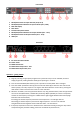
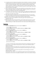

Front Panel
1. MUTE/EDIT buttons for Input channels (CH A, CH B)
2. MUTE/EDIT/LEVEL indicators for Input channels (CH A, CH B)
3. Main LCD display
4. Data wheel
5. Parameter & System buttons
6. MUTE/EDIT/LEVEL indicators for Output channels (CH 1 - CH 6)
7. MUTE/EDIT buttons for Output channels (CH 1 - CH 6)
8. USB input
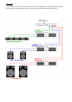
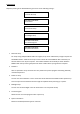
Rear Panel
9. IEC mains inlet & fuse holder
10. Power switch
11. RS485 interconnect
12. Balanced XLR outputs CH1 – CH6
13. Balanced XLR inputs CH A, CH B
Operation – getting started
1) Begin by selecting an appropriate program for the particular setup or if not available, choose an
empty program by rotating the data wheel (4) and pressing it in to select.
2) Press and hold the MUTE/EDIT button (7) for output CH1 until the yellow “EDIT” LED lights
3) Press the “GAIN” parameter button (5) and turn the data wheel (4) to select the Gain amount and
which input (A, B or A+B) is required – turning the data wheel alters the current value, pressing the
data wheel in selects and moves the curser on to the next value.
4) Select the “X-OVER” (cross-over) parameter button and, using the data wheel, select the type of filter
curve to be used (Butterworth, Linkwitx-Riley or Bessel), dB/Oct (decibels per octave or steepness)
and the cut-off frequency. Pressing the “X-OVER” button again toggles between HPF and LPF (High
Pass Filter and Low Pass Filter)
Increasing just the HPF frequency removes the low frequencies – for mid-high cabinets.
Decreasing just the LPF frequency removes the high frequencies – for low or sub cabinets
Using both HPF and LPF together creates a Mid Pass Filter – for mid cabinets
5) If required, frequencies can be cut or boosted for the selected channel by pressing the “EQ” button
and performing the parameter editing process for the 6 bands of parametric EQ