
Instruction Manual

FORM-ENG-0018 REV A 05-27-03
607 NW 27th Ave
Ocala, FL 34475
Ph: 352-629-5020 or 1-800-533-3569
Fax : 352-629-2902 or 1-800-520-3473
TECHNICAL DATA SHEET
PAGE
13 OF 26
DATE
3/28/2012
PRODUCT GROUP
THROTTLE CONTROL
P/N 117155 REV
1.23
PRODUCT
TOTAL PRESSURE GOVERNOR (TPG)
BY AMS
Manual P/N 117684
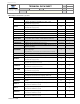
5. Governor Control Setup Menu
5.1. Engine compatibility
The factory default settings of the TPG make it “out of the box” ready to operate a Cummins engine programmed with
the Emergency Vehicle Calibration. Typically, for the default configuration no values will require modification, other
than changing the desired engine rpm, high-idle rpm and pump pressure preset values.
The governor is capable of controlling any engine that allows J1939 PGN0 (Torque Speed Control) messages from a
unique source address. These engines include various Detroit Diesel DDEC engines, Mercedes Benz (MBE)
engines, Volvo, and others. Programming of the source address or other parameters on the engine ECM may be
required. The Scania engine allows control by proprietary J1939 messages and is supported by the TPG. In cases
where an engine does not support data link control, the TPG can be configured to control the engine with an analog
signal coupled to the engine remote PTO throttle input.
Contact Class 1 or visit our website (www.class1.com) for a complete engine compatibility list.
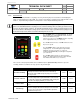
5.2. Enter the setup menu
The setup menu allows access to the configuration and calibration screens. There are 5 set up menus available:
menu level 1 (basic setup menu), menu level 2, menu level 3, menu level 4 (factory menu), and menu level 5
(restricted). All configurations and calibrations are saved in non-volatile memory and will not be lost with power
disruptions.
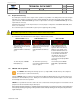
Standard menu level access
The standard menu level access method allows entry into menu levels 1, 2, or 3 only. Use the Direct menu level
access method to enter menu level 4 or 5. Once a menu level has been selected, subsequent menu access will
always enter that menu level and a system re-power is required to reset the first entry menu level.
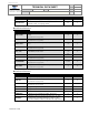
+
Display shows MENU 04 SECS and begins counting down. Continue holding IDLE and MENU
until the display shows *SETUP MENU* (4 seconds) and then release the switches. (If menu level
2 or menu level 3 is desired continue to hold the switches until the display shows the desired menu
level then release).
Press the MENU switch to cycle through the available setup menu items.
or
Press the INC or DEC switches to modify the current menu item.
Press the PRESET switch to store the configured menu item. The display will show ---STORED---.
Press the MODE switch to exit the setup menu. The display will show --EXITMENU-- and then
resume normal operation.
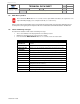
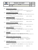
Direct menu level access
+
or
Enter a password while at idle to direct access a menu level.
INC, DEC, DEC, INC, DEC, DEC, DEC, INC = menulevel 1
INC, DEC, DEC, INC, DEC, DEC, INC, DEC = menulevel 2
INC, DEC, DEC, INC, DEC, DEC, INC, INC = menulevel 3
INC, DEC, DEC, INC, DEC, INC, DEC, DEC = menulevel 4 (factory)
INC, INC, DEC, INC, DEC, INC, DEC, INC = menulevel 5 (restricted)