Contents Table of Contents Contents ........................................................................................................... 1 Network ......................................................................................................... 2-3 Hardware ....................................................................................................... 4-5 Addresses ........................................................................................................ 6 Logic .......
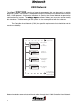
Network USM Network The Class1 ES-K ES-Keey TM Sy Syst stem st em consists of several components that can be used in a vehicle electrical system. The system is multiplexed using the Controller Area Network bus and the SAE J-1939 protocol. An electrical database is used by the Control Module to operate the vehicle electrical system. The ES-K ES-Keey TM Expr Expres esss software allows you to create, read or modify es this database. Troubleshooting of the system is also accomplished with the software.
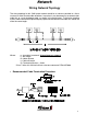
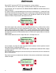
Network Wiring Network Topology The wiring topology for this CAN based network should be as close as possible to a linear structure in order to avoid cable reflections. In practice, it may be necessary to connect short cable tails to a main backbone cable, as shown in the figure below. To minimize standing waves, nodes should not be placed equally spaced on the network and cable tails should not all be the same length.
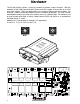
Hardware The ES-Key System utilizes a variety of modules to perform various functions. With the exception of the USM Control Module, Display and Data Logger, there can be up to 16 of each type module. They are addressed in the system by device type and number. For instance, a Power Distribution Module can exist at address 0 through F (15) and a Switch Input Module could be set at the same address since it is a different type.
Hardware There are several modules available to perform various tasks in the system. The Universal System Manager (USM) is the control module and performs load management, logic and main communications functions of the system. The USM contains the database for the system. Currently, there can be only one control module in a system. A system can contain a Digital Display Module (Display).
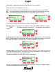
Addresses Every INPUT and every OUTPUT in the system has a unique address. That address consists of a device type, a module number and a port on that device. As an example, the first output on the first Power Distribution Module would be addressed as PDM 0, Output 0. In a typical system, it would be labelled for the load that is connected to it.
Logic Each output is operated by the logic associated with it in the database. There are three types of logic for each circuit. AND All the conditions associated with the circuit must be ON for the circuit to be ON. OR Any of the conditions associated with the circuit can be ON for the circuit to be ON. NOT The associated condition must be OFF or false for the circuit to turn ON.
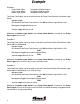
Example Example 1: Pump Panel Lights Pump Panel Switch Marker Light Switch Assigned to PDM 3 Output 0 Assigned to PDM 3 Input 0 Assigned to SIM 0 Input 0 The Pump Panel Lights are set to come on with the Pump Panel Switch or the Marker Light Switch. Multiplex Logic ON whenever the Pump Panel Switch is ON OR the Marker Light Switch is ON. Management Logic defaults to true. Vocation Logic defaults to true.
Example ESC ESC ESC ESC --SYSTEM OUTPUTS-CIR:Pump Panel Lgts POWER MOD#3 OUT-00 [MNGT] [MPLX] [INTK] --SYSTEM INPUTS-CIR: Marker Lgt Switch INPUT MOD#0 IN-00 --SYSTEM INPUTS-CIR:Pump Panel Switch POWER MOD#3 IN-00 MUX: Pump Panel Lgts• 1: Markew LT Switch OR 2: Pump Panel Switch [GO->1] [BACK] [GO->2] SCROLL ESC --SYSTEM OUTPUTS-CIR:Pump Panel Lgts POWER MOD#3 OUT-00 [MNGT] [MPLX] [INTK] SCROLL SCROLL SCROLL SCROLL MUX :Pump Panel LTS 1 :Pump LT Switch ESC SCROLL [GO->1] [BACK] ESC MUX:
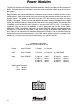
Power Modules The ES-Key System uses Power Distribution Modules (PDM’s) to supply current to electrical loads. Currently these are available in two basic styles and there can be up to 16 of them in the system. Relay Modules use standard 30/40 Amp automotive relays and are available in 8 and 12 relay configurations. Both relay boards have two relays that the common terminal can be set to discrete inputs. The power to the board must be OFF any time that the switch for these outputs is changed.
Power Modules Solid State Modules use an integrated circuit driver to supply current to its loads. Outputs are common bussed to system power and can deliver up to 7.5 Amps. Current levels above two (2) amps can be used to indicate whether an output is ON or OFF. These modules use a Hex switch for addressing and come in three (3) styles. 104434 Eight (8) output PDM-8 104528 Six output Two input PDM-(6/2) 104529 Four output Four input PDM-(4/4) Solid State Modules with inputs have polarity selectable inputs.
Motor Control The ES-Key Motor Control Module (PDM) is a solid state module capable of providing up to 15 Amps per output. It has 8 polarity selectable inputs, 8 positive outputs and 4 motor control circuits (H-bridge).
Solid State PDM Solid State Modules use an integrated circuit driver to supply current to it’s loads. Outputs are common bussed to system power and can deliver up to 7.5 Amps. Current levels above two (2) amps can be used to indicate whether an output is ON or OFF. These modules use a Hex switch for addressing and come in three (3) styles.
Switch Modules The ES-Key System uses Switch Input Modules (SIM’s) to provide switching information to the system. Currently these are available in two basic styles and there can be up to 16 of them in the system.
Switch Modules Switch Input Modules have 16 available inputs which are individually polarity selectable. These modules use a Hex switch for addressing and come in three (3) styles. 104508 Sixteen (16) Input SIM-16 104462 Sixteen Input Three Output SIM-16/3 10xxxx Sixteen Input/ One OUT/2 Analog SIM-16/1/2 All inputs are polarity selectable using DIP switches on the circuit card.
USM 103383 USM Control Module (PN 103383) The USM Control Module is the primary module in the system. It has an ES-K ES-Keey TM CCar ardd reader ar to transfer information to and from the microprocessor memory as well as the capability to interface with a computer on the CAN bus. Direct access can be made through five switches and a twenty character by four line display on the USM. These are used to access the menu driven information, programming and diagnostic features.
System Logic The ES-Key System utilizes an electrical connection database for operation. This database is written by the OEM and contains all the information necessary to operate the ES-Key System for a specific vehicle. The system can be customized to the user’s needs without changing the physical wiring or hardware. This database can be ‘read’ by the user and is an ‘as built’ wiring diagram that stays with the system.
MNGT Data ES-KEY USER MENU SELECT OPTION ESC SCROLL [UTIL] [DATA] Selecting=xa^q^z=presents the system database for review. -- SYSTEM OUTPUTS -CIR:CIRCUIT NAME ESC MODULE TYPE ADDRPORT [MNGT] [MPLX] -- SYSTEM INPUTS -CIR:CIRCUIT NAME SCROLL ESC MODULE TYPE ADDR PORT SCROLL [INTK] The scroll arrows allow you to see all of the system inputs and outputs. The top line of the display indicates whether the circuit is an INPUT or OUTPUT. The second line shows the Circuit Name.
MPLX Data ESC -- SYSTEM OUTPUTS -CIR: LIGHT BAR POWER MOD#0 OUT-01 [MNGT] [MPLX] [INTK] SCROLL Selecting [MPLX] brings up the system multiplex menu. MUX: LIGHT BAR 1: Switch LIGHT BAR ESC SCROLL [GO-1] [BACK] Pressing the [GO-1] switch takes you to the circuit menu for that argument.
INTK Data ESC -- SYSTEM OUTPUTS -CIR: LIGHT BAR POWER MOD#0 OUT-01 [MNGT] [MPLX] [INTK] SCROLL Selecting [INTK] brings up the system multiplex menu.
Fault Menu Enter the menu system by pressing the switch immediately below [MENU]. Class1, Inc. ES-KEY SYSTEM Version 2.02d [MENU] ESC ES-KEY USER MENU SELECT OPTION ESC SCROLL [UTIL] [DATA] ES-KEY Utilities ESC SCROLL [DIAG] [CARD] ES-KEY DIAGNOSTICS ESC SCROLL [OTHER] ESC [FAULTS] -SYSTEM FAULT CODESCURRENT/ACTIVE: 3 HISTORICAL LOG: 5 SCROLL ES-KEY DIAGNOSTICS ESC SCROLL [OTHER] [FAULTS] SCROLL The two main sub-menu sections are utilities and data.
Module Menu Information on çå=card, Å~êÇI fåÑçêã~íáçå= network or system? åÉíïçêâ=çê=ëóëíÉã\ ESC SCROLL [NET] [SYS] [CARD] kbq z==xpvpz==x`^oaz =xkbq kbqz==xpvpz==x`^oaz =x Select Network I/O, Modules, or Vocation ESC SCROLL [MOD] [I/O] [VOC] ESC MOD:POWER ADDR:00 STATUS: LOCATED v1.01 PDM 8-Relay Msg/sec:Tx=XX Rx=XX ESC MOD:DISPLAY ADDR:00 STATUS: LOCATED v1.
I/O-VOC Menu Select Network I/O, Modules, or Vocation ESC Selecting [I/O] brings up the input and output circuits page. SCROLL [MOD] [I/O] [VOC] Each circuit on the vehicle can be looked at by using the up and down arrows to scroll through the circuits. The screen will show whether the circuit is an INPUT or an OUTPUT and whether it is ON or OFF. CIR:LIGHT BAR OUTPUT: OFF ESC SCROLL CIR:LIGHT BAR SWITCH INPUT: ON ESC Pressing [ESC] returns you to the Select Network I/O, Modules or Vocation menu.
ENG Menu Information on çå=card, Å~êÇI fåÑçêã~íáçå= network or system? åÉíïçêâ=çê=ëóëíÉã\ ESC SCROLL [NET] [SYS] kbq z==xpvpz==x`^oaz =xkbq kbqz==xpvpz==x`^oaz =x [CARD] ESC ESC Information on load management, Engine, or database file? [ENG] [MNGT] [FILE] THROTTLE INPUT 000% OUTPUT:0.0V PWM:00% FIDLE:00% REMOTE:00% [HSET] [IDLE] [EXIT] SCROLL SCROLL CHANGE HIGH IDLE SET-POINT TO 00% ? ESC SCROLL [YES] ESC [NO] THROTTLE INPUT 000% OUTPUT:0.
MNGT Menu ESC ESC ESC ESC ESC Information on load management, Engine, or database file? [ENG] [MNGT] [FILE] LOAD MNGT: DISABLED SEQ:4 SHED:7 STG:OFF MODE A :Response VOLTS: 13.8 LOAD MNGT: ENABLED SEQ:4 SHED:7 STG:ON MODE B :Scene VOLTS: 13.8 LOAD MNGT: ENABLED SEQ:4 SHED:7 STG:ON MODE B :Scene FORCE VOLTS: 13.8 LOAD MNGT: ENABLED SEQ:4 SHED:4 STG:ON MODE B :Scene FORCE VOLTS:12.
FILE Menu ESC Information on load management, Engine, or database file? [ENG] [MNGT] [FILE] The [SYS] menu opens a selection window for information on Load Management, Engine or the database file. SCROLL Pressing [FILE] brings up a display that shows the file name and the date it was created.
USM 103383 USM Control Module (PN 103383) The USM Control Module is the primary module in the system. It has an ES-K ES-Keey TM CCar ardd reader ar to transfer information to and from the microprocessor memory as well as the capability to interface with a computer on the CAN bus. Direct access can be made through five switches and a twenty character by four line display on the USM. These are used to access the menu driven information, programming and diagnostic features.
Make Card The ES-Key Card is a memory module that contains the database for system operation. This database is written by the OEM and contains all the information necessary to operate the ESKey System for a specific vehicle. This database can be ‘read’ by the user and is an ‘as built’ wiring diagram that stays with the system. The database can be transferred to an ES-Key Card from the USM. A simple menu driven routine allows you to perform this function. Select: Select: [MENU] [UTIL] ESC Class1, Inc.
Display INFORMATION CENTER Class 1 ES-Key System ESC 11:53 SCROLL [DIAG] [UTIL] [INFO] SYSTEM UTILITIES ESC SCROLL [TIME] [U/M] ESC The Data Logger clock and the system units of measurement can be changed at the System Utilites Sub-menu. Select either date or time for a menu that will allow you to set either the time or date. Set the Data Log Date and Time SCROLL [DATE] ESC 73F Pressing the switch under UTIL brings up the System Utilities Menu.
Display ESC -- SYSTEM OUTPUTS -CIR: LIGHT BAR POWER MOD#0 OUT-01 [MNGT] [MPLX] [INTK] SCROLL MUX: LIGHT BAR 1: Switch LIGHT BAR ESC SCROLL [GO-1] [BACK] Pressing the [GO-1] switch takes you to the circuit menu for that argument. MUX: LIGHT BAR 1: Switch LIGHT BAR ESC The multiplex information screen shows the arguments that must be true for the circuit to operate. The scroll switches select different circuits. [BACK] returns you to the Circuits Menu.