
Owner's manual


2
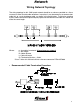
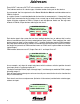
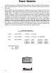
Control
Module
Switch
Module
Vocation
Module
Output
Module
Power Switching
to Loads
Main Controller
and
User Interface
Interface to
Switch Panel
Vocation Interlock
Trans/Engine
Interface
To other
J-1939 Devices
To other Devices
on the Management
Network Segment
USM Network
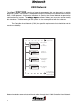
The
Class1
ES-KES-K
ES-KES-K
ES-K
ee
ee
e
y y
y y
y
TMTM
TMTM
TM
Sy Sy
Sy Sy
Sy
stst
stst
st
em em
em em
em
consists of several components that can be used in a vehicle
electrical system. The system is multiplexed using the Controller Area Network bus and the
SAE J-1939 protocol. An electrical database is used by the Control Module to operate the
vehicle electrical system. The
ES-KES-K
ES-KES-K
ES-K
ee
ee
e
y y
y y
y
TMTM
TMTM
TM
Expr Expr
Expr Expr
Expr
eses
eses
es
s s
s s
s
software allows you to create, read or modify
this database. Troubleshooting of the system is also accomplished with the software.
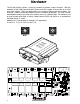
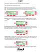
The Controller Area Network (CAN) has specific requirements that should be met for
maximum reliability.
Network modules communicate with each other through the J-1939 Controller Area Network.
Network