
Owner's manual


3
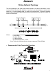
Network
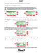
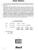
Wiring Network Topology
The wiring topology for this CAN based network should be as close as possible to a linear
structure in order to avoid cable reflections. In practice, it may be necessary to connect short
cable tails to a main backbone cable, as shown in the figure below. To minimize standing
waves, nodes should not be placed equally spaced on the network and cable tails should not
all be the same length.
Where: n= # modules in network/
30 maximum per network
L= Bus length
D= Node distance
I= Cable tail length
R
L
=Terminating resistor = 120Ω*
* Class 1 offers this resistor built into a harness connector DT06-3S-P006
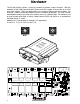
• Recommended Cable Termination Procedure: