
Owner's manual


5
Hardware
There are several modules available to perform various tasks in the system.
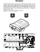
The Universal System Manager (USM) is the control module and performs load manage-
ment, logic and main communications functions of the system. The USM contains the data-
base for the system. Currently, there can be only one control module in a system.
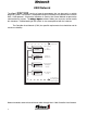
A system can contain a Digital Display Module (Display). Four pages (4 lines by 20 charac-
ters) of greetings messages and 50 pages of extended messages can be stored in the dis-
play. In addition, live information about active and inactive circuits can be displayed and it
can be used as an interface to the system.
A Modem Module (MODEM) can be added to any circuit and will allow the system to be
accessed remotely by Express Software through a serial port or modem.
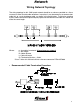
There can be up to 16 Power Distribution Modules (PDM) in a system. The PDM’s control the
loads in a circuit. They come in two basic types, electromechanical (relay boards) and elec-
tronic (solid state). They can handle from 7.5 amps up to 40 amps dependent on the exact
module specified. One of these modules is configured as an 8 input, 8 output, 4 motor driver
(H-bridge). A low current (250 mA) 16 Output Module is available for use in indicator or driver
circuits. The 16 output module comes in a variety of lowside and highside driver configura-
tions. (Power or Ground outputs)
There can also be up to 16 Switch Input Modules (SIM) in a system. These come in either 16
positive input or 16 polarity selectable input versions. Any switch or input in the system needs
to be tied to an input circuit on a module in the system.
Vocation Modules are available for interlocking and engine control tasks. These are engine-
transmission specific and there can only be one in a system.
A data logger is available that stores system fault and interlock information. It can aso be
configured to log specified circuit information. It will store 200 system faults and 6,000 events
before it loops around and overwrites the oldest data. These events are all dated and time
stamped to the nearest second. Up to 32 circuits can be tied to the data logger for trouble-
shooting or information purposes. It is also a true time clock and a temperature sensor can
be wired into it. The time is displayed on the data logger. The temperature and time are
displayed on the Display Module.
There are variations of some of the above modules available.