
Owner's manual


6
Addresses
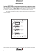
Every INPUT and every OUTPUT in the system has a unique address.
That address consists of a device type, a module number and a port on that device.
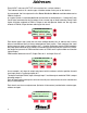
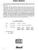
As an example, the first output on the first Power Distribution Module would be addressed as
PDM 0, Output 0.
In a typical system, it would be labelled for the load that is connected to it. If it were the Pump
Panel Lights connected to the first output, then a name (tag or label) indicating Pump Panel
Lights could be assigned to PDM 0, Output 0 and the operator would use the tag name
instead of PDM 0, Output 0 when referring to that circuit.
SCROLL
ESC
--SYSTEM OUTPUTS--
CIR:Pump Panel Lgts
POWER MOD#0 OUT-00
[MNGT] [MPLX] [INTK]
SCROLL
ESC
--SYSTEM OUTPUTS--
CIR:Rear Scene Lgts
POWER MOD#3 OUT-07
[MNGT] [MPLX] [INTK]
SCROLL
ESC
--SYSTEM INPUTS--
CIR: Pump Lgt Switch
POWER MOD#0 IN-01
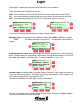
As an example, an 8 input, 8 output relay board with its address switch at position 3 would
have input ports 0-7 and output ports 0-7.
The inputs would be PDM 3, Input 0 through Input 7 and the outputs would be PDM 3, output
0 through output 7.
Each of these inputs and outputs can be and usually are named for the circuit or function that
they are connected to.
Each circuit must have a unique name (limited to 16 characters) and be tied to a device type,
address and port.
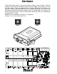
Each device type in the system that can have multiple devices has an address that is set by
either a hexadecimal (hex) or binary coded decimal (bcd) switch. Each module of the same
device type must have a unique address (0-F). A power distribution module (PDM) located in
the pump panel could be set to address 3 and would be accessed by the system as PDM 3.
Any output or input on that PDM would be known as PDM 3 and it’s port number and function
(Input/Output).
PDM module addresses are 0-F, Output Ports 0-11 and Input Ports 0-7.