
Owner's manual


8
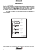
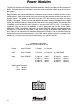
Example 1:
Pump Panel Lights Assigned to PDM 3 Output 0
Pump Panel Switch Assigned to PDM 3 Input 0
Marker Light Switch Assigned to SIM 0 Input 0
The Pump Panel Lights are set to come on with the Pump Panel Switch or the Marker Light
Switch.
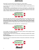
Multiplex
Logic
ON whenever the Pump Panel Switch is ON
OR
the Marker Light Switch is ON.
Management
Logic
defaults to true.
Vocation
Logic
defaults to true.
Whenever the Marker Light Switch or the Pump Panel Switch is turned on, the Pump
Panel Lights will turn ON.
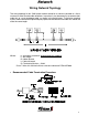
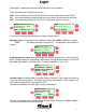
Example 2:
The Pump Panel Lights are set to come on with the Pump Panel Switch OR the Marker Light
Switch AND in Scene Mode.
Multiplex
Logic
ON whenever the Pump Panel Switch is ON
OR
the Marker Light Switch is ON.
AND
Management
Logic
set to mode B (Scene Mode).
AND
Vocation
Logic
defaults to true.
Whenever the Marker Light Switch or the Pump Panel Switch is turned on, the Pump
Panel Lights will turn ON
as long as the Park Brake is set
.
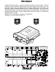
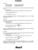
Example 3:
The Pump Panel Lights are set to come on with the Pump Panel Switch OR the Marker Light
Switch AND in Scene Mode if it is Okay to Pump.
Multiplex
Logic
ON whenever the Pump Panel Switch is ON
OR
the Marker Light Switch is ON.
AND
Management
Logic
set to mode B (Scene Mode).
AND
Vocation
Logic
set to Okay to Pump.
Whenever the Marker Light Switch or the Pump Panel Switch is turned on, the Pump
Panel Lights will turn ON
as long as the Park Brake is set
AND the pump is engaged and the
transmission is in high range lockup.
Example