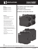
VENTILATORS VH SERIES HEAT RECOVERY VENTILATORS For New Construction MODELS: VH30160NC 30-160 CFM HRV VH70220NC 70-220 CFM HRV VH30100RNC 30-100CFM HRV VH30140RNC 30-140CFM HRV VH70220ESNC 70-220CFM HRV Installation and Operation Manual Features • Three operating modes (Intermittent, Continuous and High) • 100% variable speed • Integrated door pressure balancing taps • Quick-connect duct collar system • Advanced proportional supply fan shut-down defrost sequence • Advanced damper defrost sequence (VH3010
TABLE OF CONTENTS SAFETY CONSIDERATIONS .................................3 VENTILATION REQUIREMENTS ..........................4 i CAUTION! Do not install in a cooking area or connect directly to any appliance. Turn off all integral disconnects before servicing. Determine Your Ventilation Needs ....................... 4 FITTING EQUIVALENT LENGTHS ........................5 TYPES OF INSTALLATIONS ................................6 Direct Ducted System..............................................
SAFETY CONSIDERATIONS i= WARNING! • To reduce the risk of injury, disconnect power to the ventilation system while performing service on the unit. There are impeller wheels turning at a very high speed that must fully stop rotating prior to accessing the inside of the unit. • To reduce the risk of electric shock or fire, do not perform any service to the HRV system other than as stated in the operating manual instructions.
VENTILATION REQUIREMENTS Determine Your Ventilation Needs Good indoor air quality is based in part on the capacity of the home’s ventilation system. The two most common methods for determining the ventilation needs of a home are the Room-Count calculation method and the Air Change Per Hour calculation method. Both methods calculate an approximate ventilation rate (in CFM or L/s). These calculation methods are described on this page. A.
FITTING EQUIVALENT LENGTHS • Flex pipe equivalent length is smooth pipe x2 • Flex fitting equivalent length is smooth fitting x2 • 90° perimeter pipe elbow equivalent length = 10 ft. (3.0 m) NOTE: Where flex duct is used • 45° perimeter pipe elbow equivalent length = 5 ft. (1.52 m) NOTE: Where flex duct is used to make 45° elbow equivalent length = 10 ft. (3.0 m) • Round wall cap spring damper or screen equivalent lengths = 60 ft. (18.29 m) to make 90° elbow equivalent length = 20 ft. (6.
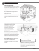
TYPES OF INSTALLATIONS DIRECT DUCTED SYSTEM From an Indoor Air Quality standpoint, this is the preferred method of installing a ventilation system in a home. This installation uses a dedicated duct system for both the supply of fresh air and exhausting of stale air accumulated in the home. With an Independent System installation, fresh air is supplied to all bedrooms and living areas and stale air is exhausted from the bathroom, kitchen and laundry room. See Figure 1.
TYPES OF INSTALLATIONS Simplified System Installation A When using this installation, make sure that there is minimum of 3 feet (0.9m) between the fresh air and exhaust air connections of the HRV/ERV in the return air duct. See Figure 3 6' (1.83 m) To living space B Make sure when using this installation that the fresh air duct connection to the forced-air system return air duct is not less than 10ft (3 m) upstream of the return plenum connection to the forced ir system.
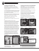
INSTALLATION Installation of the HRV / ERV Insulated Flex From Unit to Outside Wall Tip to installer: Place HRV/ERV on a stepladder to Tip to installer: To ensure a better installation and to It is recommended that approximately 16 inches of flexible duct be installed between the HRV or ERV and your rigid duct. The flexible duct is connected to the HRV or ERV in the same way as the insulated flex. All ducting to and from the HRV/ERV must be adequately insulated to minimize heat loss and gain.
INSTALLATION Condensation Drain Line Insert the threaded drain adapter through the bottom of the HRV/ERV and hand-tighten the plastic nut supplied with the drain kit. Use a wrench to tighten the nut another half turn to ensure a complete seal. Figure 12 Create a trap by forming a loop in the condensate tubing. Ensure this trap will not be exposed to temperatures where the condensate can freeze.
INSTALLATION/CONTROLS Matrix™ High-Performance Ventilation Hood Installation Exterior wall Exhaust air from home “TOP” Important: Install ventilation hood a minimum of 18" (457mm) above ground level or the anticipated snow level. Fresh air to home “BOTTOM” Do not install under a deck, enclosed porch, patio, garage, crawl space or attic.
N.C. N.O. Low Voltage HRV/ERV Controller COM CONTROLS / WIRING + RLY1 B INTERLOCK G R TIMER J2 4321 D1 SW3 – Reference: VH30160NC, VH70220NC & VH70220ESNC B1 MASTER G N.C. G G NC NO INTERLOCK R B G R N.C. B1 B SW3 R G R TIMER J2 + – VHP-T3 TIMER (3 wires) B1 N.C. N.O. COM W REMOTE G B W COM B INTERLOCK B + – W W B1 PROG N.C. B SW3 – G COM NC NO INTERLOCK N.C. N.O. G R B1 N.C. RLY1 N.O.
INSTALLATION/CONTROLS Wiring Diagrams for Furnace Interlock Systems Reference: VH30160NC, VH70220NC & VH70220ESNC N.C. N.O. RLY1 COM B INTERLOCK SW3 – MASTER W B1 R G W Y C 4321 + D1 G R TIMER J2 PROG Standard Forced-Air Interlock Wiring A relay is normally used when tying a ventilation system into the forced-air distribution system.
B1 IN Low Voltage HRV/ERV Controller Forced Air System Term CONTROLS / WIRING B SW3 G R TIMER R G W Y C R G W Y C J2 + If your thermostat operates this way, you must use the Alternate Forced-Air Wiring shown at right. N.C. 4321 D1 – N.O.
SEQUENCE OF OPERATIONS Sequence of Operations for Ventilator and Connected Wall Controls and Timer There is a low voltage ventilator control mounted on the HRV/ERV to operate the ventilator in Intermittent (INTER) or Continuous (CONT) operation. When a VHP-RD2 or VHP-TC10 wall control is connected to the ventilator, it can override the setting on the ventilator as described in the table below.
VENTILATION CONTROL Ventilation Control BALANCING Mode When the control is set to BALANCING mode, the Indicator LED turns yellow and the selector switch is used for setting the high speed of the fans for balancing purposes (Fresh supply air, Exhaust air, and Both). The options are: • INTER (Intermittent): With the selector switch in this position, the speed of the exhaust air fan can be set.
BALANCING THE UNIT Procedure for Setting High (Override) Airflow Rate and Balancing the Ventilator To balance the ventilator, you will need to independently adjust the flow rate in both the fresh air (supply) duct as well as the stale air (exhaust) duct. You will need an airflow measuring device such as a pitot tube or a Magnehelic gauge. NOTE: Turn the HVAC equipment fan ON while performing these balancing steps. 1.
BALANCING THE UNIT (Reference: VH30160NC, VH70220NC & VH70220ESNC only) TOOLS REQUIRED TO BALANCE THE HRV/ERV • A Magnehelic gauge capable of measuring 0 to 2.0 inch of water (0 to 500 Pa) and two (2) plastic hoses. • A balancing reference chart located on the HRV/ERV access door panel. CONSIDERATION WHEN BALANCING THE HRV/ERV • Seal all the unit ductwork with tape. Close all windows and doors. • Insure all exhaust devices such as range hood, dryer and bathroom fans are OFF.
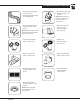
Front Devant Fresh BALANCING THE UNIT Enlever les quatre Air (4) bouchons à défoncer de nylon. Ne pas les jeter.
BALANCING THE UNIT TROUBLESHOOTING Question / Item Diagnosis / Solution • Ventilator not running • Verify breaker in main electrical panel • Verify the HRV or ERV is in the ON position • Verify all wall controls connected to the ventilator are activated to supply power to the unit • Unplug ventilator and verify that the wall control is wired correctly to the connection box on the side of the unit • Verify main outlet polarization • Air is too dry • Increase the humidity level on the wall control (Turn
MAINTENANCE Routine Maintenance 4. Clean the condensate drain and pan Seven-Step Maintenance Schedule With routine preventative maintenance, you can avoid unnecessary problems, ensure the effectiveness of your ventilator, and prolong its life. i WARNING! BE SURE TO DISCONNECT THE ELECTRICAL POWER BEFORE SERVICING YOUR SYSTEM 1. Clean or replace air filters Filters, which are located within the ventilator, should be cleaned every two to three months.
WARRANTY Limited Warranties Coverage Daikin North America LLC (“Daikin”) warrants this product, to the original consumer, to be free from defects in materials and workmanship under normal use and service, for the applicable time periods listed below.
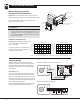
Balancing chart / Tableau d’équilibrage Fresh air Air frais d'air frais d'air vicié Balancing chart / Tableau d’équilibrage Stale air Fresh air NC NO LOW/BAS B R G B/B1 LOW/BAS TIMER / MINUTERIE Fresh air / Air frais G COM LOW/BAS NC R Stale air / Air vicié PO. d’eau (Pa) PCM L/s PCM L/s Pressure / Pression Pascal PO. d’eau (Pa) 0.
NOTES Notes IO-VENT-NC WWW.CLEANCOMFORT.
VENTILATORS Our continuing commitment to quality products may mean a change in specifications without notice. © 2017 • • Houston, Texas • Printed in the USA. 24 WWW.CLEANCOMFORT.