DM14B/C DIGIMAX USER GUIDE and MENU NAVIGATION COMBINED DIGITAL & ANALOG PROFESSIONAL ANALYZERS FOR: RADIO, TV, CATV & SATELLITE 4-2250 MHz QPSK-COFDM-QAM-MPEG Subject to change without notice
DM-14B & DM-14C User’s Guide Code: UG-DM14B-14C Title: DM14B & DM14C User’s Guide Edition: 1.16/2.0-EN/1.
DM-14B & DM-14C User’s Guide INDEX Useful Suggestions ........................................................................................................................... 5 Satellite Dish pointing (Sat Point Function) ...................................................................................... 11 Configuration Menu ........................................................................................................................
DM-14B & DM-14C User’s Guide FILE FILE FILE FILE FILE FILE Manager Manager Manager Manager Manager Manager FILE ........................................................................................................................ 67 INFO ....................................................................................................................... 68 SHOW ..................................................................................................................... 69 RENAME ............
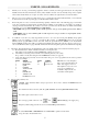
DM-14B & DM-14C User’s Guide USEFUL SUGGESTIONS 1) Thank you for choosing our measuring equipment, which is currently used and appreciated by the most important Satellite Service Providers, Broadcasters and by many installers, because it is user friendly and provides complete and accurate measurements. On our part, we will do our best to fulfil your requirements now and in the future. 2) This is a new concept, quick user guide that is easy to consult.
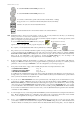
DM-14B & DM-14C User’s Guide To select PLAN–PRG–CHAN–FREQ decrease, etc To select PLAN–PRG–CHAN–FREQ increase, etc. To activate, confirm and/or quit the various menus, measurements or settings (keep pressed for 2” to activate the numerical keyboard and the scroll menu) Activates, in cycles, the various measurement levels. Activates/disactivates the various menus related to the activated function. N.B.
DM-14B & DM-14C User’s Guide volume of the keys’ beep sound. To exit CONFIG. MENU press ESCAPE/MEAS. Please avoid using the cancellation menu of the memory banks until you are confident with the use of the meter. 13) Now let us take a look at the SPECIAL MENU (see page 13).
DM-14B & DM-14C User’s Guide • • • • • • • 17) PICTURE: spectrum with outlines only or full white ∆ MARKER: freq./level difference between two signals and C/N measurement MARKER BW: to adjust filters, amplifiers, etc. and to measure digital power in SPECT mode “BW–PWR”. MAX HOLD: peak memory. Maintains the max. peak reached during a series of measurements DC at RF in: output power supply (5, 12, 15, 18, 24 V – OFF). LNB L.O.: local oscillator.
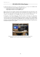
DM-14B & DM-14C User’s Guide N.B. With reference to fig. 8, the NETWORK name you can read in the centre to the right, e.g. NETNAME=SKY, is the NET.ID table transmitted via satellite by the operator and which the instrument reads by extracting the information from the MPEG data. However, the prog. name, read in the centre to the left under the word MENU, e.g. PROG NAME: SKY1, is the one you, or your dealer, has pre-stored and can be varied only using a PC, opt. (see page 19). N.B.
DM-14B & DM-14C User’s Guide DM-14B & DM-14Color Digimax The DM-14B and DM-14Color meters allow you to visualise digital pictures of non-encrypted services (FREE-TO-AIR), contained in the digital signals received at the RF input of the meter, in other words: - Digital transponder transmitted via satellite with QPSK encryption, - Digital multiplex transmitted via ether with COFDM encryption, - Digital multiplex transimitted via cable with QAM encryption.
DM-14B & DM-14C User’s Guide SATELLITE DISH POINTING (SAT POINT function) As this is a function which is used often and is, at the same time, facilitated by our automated high-resolution spectrum, we thought we would dedicate a chapter to this subject (please also refer to the “QPSK” SPECTRUM). a) Activate SAT mode, analog or QPSK (whichever you prefer).
DM-14B & DM-14C User’s Guide i) Now select 1 or 2 dB/DIV (in the lower right hand corner); in this configuration you have maximum spectrum resolution, which allows you to perfect your dish pointing. If the carriers go over the reference level, increase it by 1 or 2 dB to see all the transponder peaks. j) At this point, return to 5 dB/div., you could also press the MENU key and activate MAX HOLD, bringing it to ON, press MENU again to remove the descriptions.
DM-14B & DM-14C User’s Guide CONFIGURATION MENU Keep pressed (hold) for 2 seconds 13
DM-14B & DM-14C User’s Guide SPECIAL FUNCTIONS MENU & VIDEO TEST PATTERN GENERATOR 14
DM-14B & DM-14C User’s Guide PROGRAM STORE MENU (MEMORY) 2” to Store The MEMORY MENU is very easy to use and is required to store programs. Basically, if you rotate the encoder, you move the cursor (grey background) to the line that corresponds to the parameter to be adjusted, for example QPSK as shown below. Press the encoder and it will position on the value of the parameter/status you want to adjust/store. (See example under the frequency line).
DM-14B & DM-14C User’s Guide PROGRAM STORE SAT MENU (MEMORY) EXAMPLES RADIO MEMORIZATION MENU EXAMPLES 16
DM-14B & DM-14C User’s Guide PROGRAM STORE TV MENU (MEMORY) EXAMPLES 17
DM-14B & DM-14C User’s Guide ANALOG TV MEASUREMENT How to reach measurement mode: DIRECT = From any previously stored "PLAN" & AN. TV "PRG" you are already in AN. TV meas (analog terrestrial TV measurement). NAVIGATION = Press rotate the encoder and select then navigate in the parameters at the top of the screen, which can be reached directly using the respective keys, or by rotating the encoder pr Press to confirm the selection. MORE MEAS N.B.
DM-14B & DM-14C User’s Guide VIDEO LINES FUNCTION ( To visualise the synchro. active area and synchro oscilloscope and all the video lines) (Useful for Analog TV and SAT and Video signals coming from a Scart socket) THE MAIN OBJECTIVE OF THE MEASUREMENT IS: to analyse the SYNCHRO area of a video line in the amplitude dominium, to visualise eventual interferences or reflections, as well as signal distortions and compressions. DIRECT: To activate the H-Sync function, press the key for two seconds.
DM-14B & DM-14C User’s Guide H-SYNC FUNCTION FOR DM-14B (Visualisation of the Analog TV & SAT synchro. active area ) DIRECT: To activate the H-SYNC function, by pressing the Photo Description key for 2 seconds, select SYNC AREA using the encoder. The picture is moved and the synchro graphic generated, locked to the signal received, to show the function “visualisation of the active synch area”.
DM-14B & DM-14C User’s Guide S/Nw MEASUREMENT FOR DM-14C – Being prepared 21
DM-14B & DM-14C User’s Guide DEMODULATED “COFDM” DIGITAL TV MEASUREMENT The COFDM measurement can be demodulated or emulated by selecting from the configuration menu (see “Configuration Menu” on page 12). How to reach measurement mode: DIRECT = From any previously stored "PLAN" and COFDM "PRG" you are already in COFDM meas. (digital terrestrial TV).
DM-14B & DM-14C User’s Guide DEMODULATED “COFDM” DIGITAL TV MEASUREMENT: “CONSTELLATION” How to reach measurement mode: DIRECT = From any previously stored “PLAN" and COFDM "PRG” you are already in COFDM meas. (digital terrestrial TV). NAVIGATION = Press press rotate the encoder and rotate the encoder and select , then press and Using the encoder select “Constell.” to activate the constellation.
DM-14B & DM-14C User’s Guide . DEMODULATED “COFDM” DIGITAL TV MEASUREMENT: “SERVICES” The COFDM measurement can be demodulated or emulated, this setting has to be selected in the configuration menu (see “Configuration Menu” on page 12). How to reach measurement mode: DIRECT = From any previously stored “PLAN" and COFDM "PRG” you are already in COFDM meas. (digital terrestrial TV).
DM-14B & DM-14C User’s Guide COFDM PARAMETERS AUTOMATIC SEARCH HELP FUNCTION With this function it is possible to automatically search, with the signal connected, the main parameters to lock the terrestrial digital signal, after having selecting the plan and program number. How to reach HELP function: DIRECT = from any "PLAN" and COFDM "PRG", press NAVIGATION = Press rotate the encoder carry out the search to directly enter the memorization menu.
DM-14B & DM-14C User’s Guide EMULATED “COFDM” DIGITAL TV MEASUREMENT The COFDM measurement can be demodulated or emulated by selecting this mode from the configuration menu (see “Configuration Menu” section on page 12). How to reach this measurement: DIRECT = From any previously stored “PLAN" and COFDM "PRG" you are already in COFDM (digital terrestrial TV).
DM-14B & DM-14C User’s Guide DEMODULATED “QAM” DIGITAL TV MEASUREMENT: (demodulator opt.) How to reach this measurement: DIRECT = from any “PLAN" and prestored QAM "PRG” you are already in QAM measurement (digital cable TV ). NAVIGATION = Press rotate the encoder select which can be reached using the appropriate keys, or by rotating the encoder then navigate in the various parameters at the top of the screen, pressing it to confirm the selection. N.B.
DM-14B & DM-14C User’s Guide DEMODULATED “QAM” DIGITAL TV MEASUREMENT: “CONSTELLATION” (demodulator opt.) How to reach this measurement: DIRECT = from any "PLAN" and prestored QAM "PRG" you are already in QAM measurement (digital TV via cable). NAVIGATION = Press rotate the encoder Select “Constell.” press select press the keys and rotate the encoder then using the encoder to activate the constellation.
DM-14B & DM-14C User’s Guide DEMODULATED “QAM” DIGITAL TV MEASUREMENT: “SERVICES” (demodulator opt.) How to reach this measurement: DIRECT = from any "PLAN" and prestored QAM "PRG" you are already in QAM measurement (digital cable TV). NAVIGATION = Press and with select , press the following keys: To obtain the list of services contained in the QAM multiplex, use the encoder and press < to select a service. Activate the function INFO to visualise the data of the chosen service.
DM-14B & DM-14C User’s Guide QAM PARAMETERS AUTOMATIC SEARCH HELP FUNCTION With this function it is possible to automatically search for the Symbol Rate of a selected program in a memory Plan, in an RF QAM multiplex. How to reach the HELP function: DIRECT = From any "PLAN" and QAM "PRG" press NAVIGATION = Press with and you directly enter the memorization menu. select carry out the search using .
DM-14B & DM-14C User’s Guide EMULATED “QAM” DIGITAL TV MEASUREMENT The QAM measurement can be emulated or demodulated (opt.) by selecting this mode from the configuration menu (see “Configuration Menu” section on page 10). How to reach the measurement: DIRECT = from any previously stored “PLAN" and QAM "PRG" you are already in QAM measurement (digital cable TV).
DM-14B & DM-14C User’s Guide DEMODULATED “8VSB” DIGITAL TV MEASUREMENT (optional demodulator) How to reach the measurement: DIRECT = From any "PLAN" and pre-memorised 8VSB "PRG", go to 8 VSB measurement. NAVIGATION = Press by rotating the encoder select and then navigate in the parameters at the top of the screen, which can be directly reached using the appropriate keys, or rotate the encoder then press to confirm the selection. = FURTHER MEASUREMENTS N.B.
DM-14B & DM-14C User’s Guide DEMODULATED “8VSB” DIGITAL TV MEASUREMENT: “CONSTELLATION” (opt. demodulator) How to reach the measurement: DIRECT = From any "PLAN" and prememorised 8VSB "PRG" you are already in the 8VSB measurement. NAVIGATION = Press rotate the encoder select “Constell.” press select then press and rotate the encoder and to activate the constellation.
DM-14B & DM-14C User’s Guide DEMODULATED “8VSB” DIGITAL TV MEASUREMENT: “SERVICES” (optional demodulator) How to reach the measurement: DIRECT = From any "PLAN" and prememorised 8VSB "PRG" you are already in the 8VSB measurement. NAVIGATION = Press and with select , then press the following keys To obtain the list of services contained in the QAM multiplex use the encoder and press to select a service. Activate the INFO function to visualise the data of the chosen service.
DM-14B & DM-14C User’s Guide HELP FUNCTION & AUTOMATIC SEARCH FOR 8VSB PARAMETERS (optional demodulator) With this function it is possible to automatically search the Symbol Rate of a selected program in a memory Plan in an RF QAM multiplex. How to reach the HELP function: DIRECT = from any "PLAN" and "PRG" 8VSB by pressing NAVIGATION = Press with select search using the encoder and you directly enter the memorisation menu. . press and set the plan and program.
DM-14B & DM-14C User’s Guide FM RADIO MEASUREMENT How to reach the measurement: DIRECT = From any previously stored “PLAN" and FM RADIO "PRG" you are already in FM RADIO mode. NAVIGATION = = Press and rotate the encoder then select and navigate in the parameters in the top of the screen, which can be reached using the appropriate keys, or rotate the encoder 36 press to confirm the selection.
DM-14B & DM-14C User’s Guide DAB (Digital Audio Broadcast) MEASUREMENT How to reach this measurement: DIRECT = from any "PLAN" and stored DAB "PRG" you are already in DAB measurement. NAVIGATION = = Press rotate the encoder select and then navigate in the various parameters at the top of the screen, which can be reached using the appropriate keys, or rotate the encoder 37 then press to confirm the selection.
DM-14B & DM-14C User’s Guide ANALOG SAT MEASUREMENT How to reach the measurement: DIRECT = From any previously stored “PLAN" and AN.SAT "PRG" you are already in AN. SAT mode (Analog Satellite). NAVIGATION = = Press rotate the encoder select and then navigate in the various parameters at the top of the screen, which can be reached using the appropriate keys, or rotate the encoder 38 then press to confirm the selection.
DM-14B & DM-14C User’s Guide DEMODULATED DIGITAL SAT “QPSK” MEASUREMENT How to reach the measurement: DIRECT = From any previously stored “PLAN" and QPSK "PRG" you are already in QPSK mode (Digital Satellite). NAVIGATION = = Press rotate the encoder select and then navigate in the various parameters at the top of the screen, which can be reached using the appropriate keys, or rotate the encoder then press to confirm the selection. N.B. The NETWORK name on the right window, e.g.
DM-14B & DM-14C User’s Guide DEMODULATED DIGITAL SAT “QPSK”: “SERVICES” How to reach the measurement: DIRECT = From any previously stored “PLAN" and QPSK "PRG", you are already in QPSK (Digital Satellite). NAVIGATION = Press with select then press the following keys To obtain a list of the services contained in the digital transponder. Use the encoder and press to select a service. Activate INFO to show the data of the chosen service.
DM-14B & DM-14C User’s Guide QPSK PARAMETERS AUTOMATIC SEARCH HELP FUNCTION With this function it is possible to automatically search for the symbol rate, with the signal connected and after having selected the plan and program number, and then store the channel. How to reach the HELP function: DIRECT = From any "PLAN" and QPSK "PRG" QPSK press si to enter directly into the memorisation menu. NAVIGATION = Press press with select .
DM-14B & DM-14C User’s Guide ANALOG TV SPECTRUM How to reach spectrum function: DIRECT = For any previously stored "PLAN" and AN. TV "PRG" press NAVIGATION = Press with select and you go directly to analog TV spectrum mode. and then press to go to analog TV spectrum. N.B. In analog TV the 10 MHz SPAN always shows the marker on the video carrier and in the centre of the channel in the centre of the display. The other SPAN values always show the Marker in the centre of the display.
DM-14B & DM-14C User’s Guide “COFDM-QAM-8VSB” SPECTRUM (Digital TV) How to reach spectrum mode: DIRECT = From any previously store "PLAN" and COFDM/QAM PRG, press NAVIGATION = Press with select e and you go directly to digital TV spectrum mode. then press and go to digital TV spectrum. .
DM-14B & DM-14C User’s Guide FM RADIO SPECTRUM How to reach spectrum mode: DIRECT = from any previously stored "PLAN" and FM RADIO "PRG" press NAVIGATION = Press with select and you go directly to Radio Spectrum (analog TV). and then press and go to radio spectrum (analog TV).
DM-14B & DM-14C User’s Guide DAB SPECTRUM (Digital Audio Broadcast) How to reach the spectrum function: DIRECT = from any "PLAN" and prestored DAB "PRG", press NAVIGATION = Press with select and you go directly to DAB spectrum. and then press 45 to go to DAB spectrum.
DM-14B & DM-14C User’s Guide ANALOG SAT SPECTRUM How to reach spectrum mode: DIRECT = from any previously stored “PLAN" and AN. SAT "PRG" press NAVIGATION = Press with select a and go directly to analog SAT spectrum mode. and then press 46 to go to analog SAT spectrum.
DM-14B & DM-14C User’s Guide “QPSK” SPECTRUM (Digital SAT) How to reach spectrum function: DIRECT = From any previously stored "PLAN" and QPSK "PRG" press NAVIGATION = Press with select e and you go directly to digital SAT spectrum. then press to go to digital SAT spectrums.
DM-14B & DM-14C User’s Guide V.SAT SPECTRUM MODE How to reach Spectrum mode from a SAT programme: NAVIGATION = Press with select e to go to the V. SAT Spectrum function.
DM-14B & DM-14C User’s Guide SAT POINT SPECTRUM MODE (See descriptions on pages 10-11) How to reach spectrum mode from a SAT: NAVIGATION = Press with select and go to the SAT POINT spectrum function.
DM-14B & DM-14C User’s Guide Δ MRK SPECTRUM MODE (Level or frequency “Δ” (difference) ratio measurement, with manual frequency selection) How to reach ΔMRK spectrum mode: DIRECT = from any previously stored “PLAN” and SAT or TV “PRG” press To activate ΔMRK mode. NAVIGATION = Press Press Press with and you will go directly to spectrum. Press select the required function: to go directly to spectrum mode. Press with then Select the programme or channel or frequency. to activate the ΔMRK function.
DM-14B & DM-14C User’s Guide Δ MRK-C/N SPECTRUM MODE (Signal/noise ratio measurement of analog signals with manual selection of noise frequencies) How to reach ΔMRK-C/N spectrum mode: DIRECT = From any previously “PLAN” & SAT or TV “PRG” mode, press NAVIGATION = Press Press Press with select the mode required: to go directly to Spectrum mode. Press with to go directly to spectrum. Press with Select the programme or the channel or the frequency required. to activate the Δ MRK-C/N function.
DM-14B & DM-14C User’s Guide MRK BW SPECTRUM MODE (Triple marker for the calibration of filters, amplifiers, etc. in SAT and TV band) a) Measurement objective: Filter, amplifiers, etc. calibration in the SAT and TV band. b) Accessories and/or necessary devices (opt.) required: - TS1 CNG calibrated noise generator - Assortment of very short, high quality cable, preferably already equipped with semi–professional connectors.
DM-14B & DM-14C User’s Guide SPECTRUM FUNCTION MRK BW PWR (Triple marker to measure the power according to the bandwidth (S.R.) of TV and SAT digital bouquets) How to reach the Spectrum MRK BW PWR mode: DIRECT = from any previously stored “PLAN” and SAT or TV “PRG” press MRKBW-PWR function. NAVIGATION = Press with select the desired mode: Press to go directly to Spectrum. Press Press again to remove the menu window. with and you directly to Spectrum. Press with .
DM-14B & DM-14C User’s Guide LIVE & RECALL SPECTRUM FUNCTION This function allows you to simultaneously visualise the stored spectrum, using the SAVE operation, and the real time spectrum received at the RF input of the instrument (live spectrum vision). LIVE: to activate this function, in spectrum mode, press the then press key, recall the spectrum vision previously saved, press , select LIVE & RECALL mode again to remove the Menu window. Recall spectrum contour N.B.
DM-14B & DM-14C User’s Guide SCROLL MENU FUNCTION The SCROLL MENU function allows the fast selection of tuning parameters by activating a scroll menu where all the possible parameters are listed. In the AN. TV, COFDM, QAM modulations it is possible to change: • in measurement mode the MODE, PLAN, PROG and CHAN, • with the MEMORY function it is possible to adjust the channel. In the QPSK, AN. SAT, DAB and FM modulations it is possible to change: • in measurement mode the MODE, PLAN and PROG.
DM-14B & DM-14C User’s Guide SPECIAL TV BARS SCAN FUNCTION The BARS SCAN function activates the graphics representation of the bar spectrum. Each bar shown represents the value of the level/average power of TV programes (analogue or digital) stored in the chosen memory plan. This spectrum representation is useful in the TV band to easily equalise a channelised head-end output.
DM-14B & DM-14C User’s Guide SPECIAL RPL SPECTRUM FUNCTION (return path) The RPL function activates a special spectrum for the measurement of channels in the return path.
DM-14B & DM-14C User’s Guide SAT FINDER – Being prepared 58
DM-14B & DM-14C User’s Guide SPECIAL REFLECTOMETER BRIDGE FUNCTION (to measure a short-circuit or interruption in coaxial cables) a) Measurement objective: to measure a short-circuit or open-circuit or a mismatch location distance in coaxial cables. b) Necessary accessories and devices (optional.): a. CNG 70DL calibrated noise generator b.
DM-14B & DM-14C User’s Guide f) Measurement example: - Recall from the menu window the previously saved cable number or insert it manually if the distribution under test uses a type of cable with parameters which are different from those saved. Menu setting: Cable number, type, propagation speed and measurement unit. - Using the “UP”, “DOWN” and “ENTER” keys, position Marker 1 in a curve dip and Marker 2 in the curve dip nearest to Marker 1.
DM-14B & DM-14C User’s Guide FUNCTION: COMMAND FOR DiSEqC 1.2 ROTOR To activate the function: In QPSK measurement, after you have set the polarization, frequency, symbol rate and local oscillator, press Select “Motor” , press and to activate the function (see figure 1). (Figure 1) To select the commands, position the cursor on ACTION and press • • • • , then select the type of command using MOVE: motor rotation per step. GOTO: rotation in the position saved in the memory.
DM-14B & DM-14C User’s Guide DESCRIPTION OF THE VARIOUS FUNCTIONS: MOVE COMMAND: Position the cursor on the word EAST or WEST, press the Press the key for a WEST rotation. key for an EAST rotation. GO TO COMMAND: Position the cursor on the position number using APPLY? And press and select the position. Position on , wait for the positioning to end. STORE COMMAND: Position the cursor on the position number using STORE? and press and select the position. Position on to store.
DM-14B & DM-14C User’s Guide FAST & ADVANCED AUTOSCAN FUNCTION (AUTOMATIC TV SEARCH) The Autoscan function is required to carry out the automatic scan of a channel plan, to search for Analog, Digital COFDM and QAM (if the optional board is fitted) TV channels and to automatically store them in a memory plan. You can chose two types of autoscan modes: Fast and Advanced.
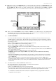
DM-14B & DM-14C User’s Guide HOW TO ACTIVATE THE FUNCTION: To start scanning select, using the encoder “Auto Scan TV”, set the Destination plan (DESTIN.) and the threshold level (LEV/POW), as shown below: Figure 2: Scan example Set the configuration parameters in the AUTOSCAN MENU selection table: • • • Press SOURCE: the channel plan, which is active in the meter, is automatically shown. DESTIN.: select the Plan where to save the Auto Scan. LEV/POW.
DM-14B & DM-14C User’s Guide DATA LOGGER “MEASUREMENT” SAVE With this function it is possible to automatically carry out als the measurements on all the channels stored in a chosen frequency plan. The measurements are saved in the memory so they can be used and printed at a later date. How to reach this function: DIRECT = Press in measurement mode. This example shows Logger 1 being saved on Plan 10. To start scanning the plan press N.B.
DM-14B & DM-14C User’s Guide DATA LOGGER “MEASUREMENT”: RECALL How to reach this function: DIRECT = Press This function is used to recall a DATA LOGGER which has been previously stored, in order to be able to analyse it on a video screen or print it.
DM-14B & DM-14C User’s Guide FILE MANAGER “FILE” The “Manager” function allows you to visualise a list of all the files stored inside the meter, to see their characteristics and carry out maintenance.
DM-14B & DM-14C User’s Guide FILE MANAGER “INFO” (First read the FILE MANAGER: “FILE”) The “INFO” function allows you to visualise the characteristics of the previously selected file. Select a file and activate INFO using the key and press Press to scroll the whole list. EXAMPLE: List showing the contents of the programs in the “Test AGO” plan, where programmes 11 to 22 are shown. Four are QAM, two COFDM treeFM Radio and tree ANALOG TV.
DM-14B & DM-14C User’s Guide FILE MANAGER “SHOW” (First read the page FILE MANAGER: “FILE”) The “SHOW” function allows you to visualize the measurements/spectrum relative to the program of the selected file. Select a file and active SHOW using the keys and press EXAMPLE: View of PROG 1 in memory plan 3 (when there is an antenna signal the measurements are carried out in real time). EXAMPLE: View of Data Logger 1 file PROG 27.
DM-14B & DM-14C User’s Guide FILE MANAGER “RENAME” (First read the page FILE MANAGER: “FILE”) The “RENAME” function allows you to only change the names of MEM. PLAN and spectrum files. Select a file, activate RENAME using the keys and press EXAMPLE: Rename the MEM PLAN file called “test lab” Select using the keys the letter required and confirm using the key. The cursor will move to the next letter. Select: To store the file name; If you do not want to change the original name.
DM-14B & DM-14C User’s Guide FILE MANAGER “DELETE” (First read the page FILE MANAGER “FILE”) The “DELETE” function allows you to cancel a custom file, logger or spectrum from the meter’s memory. This function allows you to remove old memory plans, data loggers and spectrums which are no longer used. Select a File, activate DELETE using the keys and press EXAMPLE: Delete the MEM. PLAN file called “hotel 01” Select: To eliminate the selected file; If you do not want to eliminate the selected file.
DM-14B & DM-14C User’s Guide FILE MANAGER “DEFRAG” (First read the FILE MANAGER “FILE” page) The “DEFRAG” function allows you to optimize and compact the meter’s memory. We suggest using this function after you have repeatedly created and cancelled memory plans, Data Loggers and spectrums. Activate the DEFRAG function using the With the keys and press keys select: To defragment the memory If you do not want to defragment the memory Press to confirm.
DM-14B & DM-14C User’s Guide APPENDICES A1 - TECHNICAL SPECIFICATIONS ANALOG TV • • • • • • • • • • • • • • • • Frequency band: 4–878 MHz including IF 38.0/38.9/45.75 MHz which can be measured, seen and heard on the TV monitor Direct selection of: memory plan, program, chan., dc at RF IN, freq.
DM-14B & DM-14C User’s Guide QAM & 8VSB (Emulated) (supplied when optional DEMODULATED QAM & 8VSB board is not inserted) • QAM frequency band: 4–878 MHz • Direct selection of: memory plan, program, chan., dc at RF IN, freq.
DM-14B & DM-14C User’s Guide 8VSB (Demodulated) • • • • • • • • 8VSB frequency band: 47–878 MHz Direct selection of: memory plan, program, chan., dc at RF IN, freq., with numerical keyboard Memorization of: memory plan, program, channel, dc at RF IN, frequency, constellation, symbol rate, frequency offset Frequency resolution: 62 KHz Input impedance: 75 ohm Interchangeable input connector: "F" or "IEC" or "BNC" ("N" optional) Power supply at RF IN: in the TV band for preamp.
DM-14B & DM-14C User’s Guide • Power measurement accuracy: 1 dB typ. (2 dB max.) with SW corr. (after 5 mins' warm-up) • MER measurement accuracy: up to 30/32 dB accuracy, 1 dB typ. (1.5 dB max), with > 40 dBuV power • Measurement filter BW: 130 KHz at –3 dB • Measurement stability versus temperature between –10 and 50°C: 0.
DM-14B & DM-14C User’s Guide VIDEO ANALYSIS & MEASUREMENTS (SYNCHRO & I.T.S. VIDEO LINES) • Visualization of the synchro and burst, according to time and amplitude • Selection and visualization of all the video lines and ITS expandible with Zoom • S/N-W measurement TV SPECTRUM ANALYSIS • • • • • • • • • • Frequency band: 4–878 MHz Span in TV band: 2–5–7–10–20–50–100– 200–500–FULL–VHF–UHF Span in RP band: 2–5–7–10–20–50–RP (4–65 MHz) dB/div: 1–2–5–10 Dynamic range: >60 dB Measurement resolution: 0.
DM-14B & DM-14C User’s Guide OTHERS • RF input power feed: – In the TV band for preamplifier: OFF, +5, +12, +15, +18, +24 V (0.3 A) – In the SAT band for LNB: OFF, +13 V, +18V, 22 KHz (0.3 A) • DiSEqC: 4, 8, 12 or 16 polarizations, DiSEqC "a.b.c.d" already pre–programmed in sequence and very easy to use.
DM-14B & DM-14C User’s Guide MEASUREMENTS • DC AT RF IN (LNB) current measurement: 0–300 mA, precision ± 3 mA typ. (5 max) • TXT selection and visualisation • Voltmeter measurement: AC 110V max, DC +110V max, applied at the RF input, precision ± 1 V typ. (2 V max) IMPORTANT: Please kindly note that if there are pixels turned off on the 5.5” TFT Monitor, fitted in ROVER instruments, the tollerance indicated by the manufacturer is 1 pixel in the centre area and 2 pixels around the parameter.
DM-14B & DM-14C User’s Guide A2 – SMART PROGRAM HOW TO INSTALL THE SMART PRO PROGRAM IN YOUR PC. a) Download the S.M.A.R.T. program from the ROVER website (www.roverinstruments.it) on the product support page, to your computer desktop. The file containing the SMART program is zipped and can unzipped using the Unzip® or Winzip® computer programs. b) The unzip program will ask for a password, which can be obtained by contacting ROVER by telephone or e-mail info@roverlaboratories.it.
DM-14B & DM-14C User’s Guide 1.0 HOW TO CONNECT YOUR MEASURING INSTRUMENT TO A PC This procedure allows the SMART program to recognise the instrument connected to the PC. 1.1 SIMPLE PROCEDURE INSTRUMENT – PC CONNECTION 1. 2. 3. 4. 5. Connect your instrument to the PC Turn on your instrument Start the Smart program Click (See Instrument Bar Description) (also see 1.4 warning paragraph) Follow the instructions shown on the screen until it is complete. 1.2 DETAILED PROCEDURE 1.2.
DM-14B & DM-14C User’s Guide 2.0 FIRMWARE UPGRADES This procedure allows you to upgrade your meter with the last Firmware version available on our website. 2.1 SIMPLIFIED PROCEDURE FIRMWARE UP-GRADE 1. Download the internet up-grade. 3. Connect your instrument to a PC. 4. Start the SMART program. 5. Click on (See instrument bar description) (also see paragraph 2.4 WARNINGS). 6. Follow the instructions on the screen until the procedure has been completed. 2.2 DETAILED PROCEDURE 2.2.
DM-14B & DM-14C User’s Guide Figure 2.1 2.3 NOTES a) When the up-grade has been correctly completed the PC screen will show the words “Program Successful” and a summary window showing the instrument settings. b) Check the new firmware version number in the Start Up screen or self-test windows. 2.4 WARNINGS a) b) c) Do not use the instrument during the up-grade procedure. If the up-grade procedure does not work check connections and repeat the operation If the operation continues to fail, contact Ro.Ve.
DM-14B & DM-14C User’s Guide 3.0 GET SCREEN This function allows you to transfer any data display from your instrument to a PC. 3.1 SIMPLIFIED PROCEDURE GET SCREEN 1. Carry out all the necessary connections (see paragraph 1.0) 1. Click on (See instrument bar description) 2. Wait for the display to appear on the PC monitor. 3. Select one of two options: - Print from the PC by pressing from the instrument bar (see 3.2.2); - Save it on the PC by pressing from the instrument bar (see 3.2.
DM-14B & DM-14C User’s Guide 4.0 “INSTRUMENT FILE MANAGER” (DATA LOGGER TRANSFER) This operation allows you to transfer a Data Logger from your measuring instrument to a PC and then print it or save it in a file. 4.1 SIMPLIFIED PROCEDURE HOW TO TRANSFER A DATA LOGGER FROM AN INSTRUMENT TO A PC 1. Carry out all the necessary connections (see paragraph 1.0) 2. 3. 4. 5.
DM-14B & DM-14C User’s Guide Figure 4.2 4.2.4 a) b) c) d) HOW TO DELETE A DATA LOGGER Open the Logger folder (See Fig. 4.1), Select from the “Instrument File Manager” window the logger file you want to delete, Press the “Delete” key in the “Instrument File Manager” window, The file will be cancelled on instrument. 4.2.5 a) b) c) d) e) f) g) HOW TO EXPORT A DATA LOGGER IN AN EXCEL SPREADSHEET Open the logger folder (See Fig. 4.1 and 4.
DM-14B & DM-14C User’s Guide 5.0 INSTRUMENT FILE MANAGER This allows you to transfer a spectrum, saved previously on your meter, to a PC in order to be able to print it or save it on your PC. HOW TO TRANSFER A SPECTRUM 1. Carry out all the necessary connections (see paragraph 1.0) 2. Click on (See instrument bar description) 3. Wait for the complete file list to download on your instrument 4. Open the Spectrum folder and open the Spectrum file (See Fig. 4.1) 5.
DM-14B & DM-14C User’s Guide 5.2.4 a) b) c) d) HOW TO DELETE A SPECTRUM Open a spectrum file, Select from the “Instrument File Manager” window the spectrum file you want to delete Press the “Delete” key from the “Instrument File Manager” window, The file will also be cancelled in the instrument. 5.2.5 a) b) c) d) e) f) HOW TO EXPORT A SPECTRUM IN EXCEL FORMAT Open a spectrum file (See 5.
DM-14B & DM-14C User’s Guide 6.0 HOW TO INSERT USER DATA This function allows you to insert user data in your meter (for example: company name, address, telephone number, etc.). This data is shown in documents during printing (for example: logger file, memory and channel plan, spectrums, etc.). 6.1 SIMPLIFIED PROCEDURE HOW TO INSERT USER DATA 1. Carry out all the necessary connections (see paragraph 1.0) 2. Click on 3. Wait for the complete file list to download from your meter 4.
DM-14B & DM-14C User’s Guide a) Once the file opens (Fig. 6.1) you can write by clicking twice on the line required, b) The compilation window opens; insert the text required and confirm by pressing “OK”, c) Fill in and/or modify the 13 lines one at a time following the same procedure. 6.2.3 a) b) c) HOW TO SAVE A FILE IN YOUR INSTRUMENT Fill in the table. On the right-hand side of the window, shown in Fig. 6.1, name the file in the USERdata Properties sections. Click on the “PC-Instrument” (Fig. 6.
DM-14B & DM-14C User’s Guide 7.0 INSTRUMENT FILE MANAGER (MEMORY PLAN MANAGEMENT) This function allows you to transfer and manage a Memory Plan on your PC in order to be able to modify and print it. 7.1 SIMPLIFIED PROCEDURE MEMORY PLAN MANAGEMENT 1. Carry out all the necessary connections (see paragraph 1.0) 2. Click on (See instrument bar description) 3. Wait for the complete file list to download from your meter 4. Open the Mem. Plan folder (see Fig. 7.1) 5. Select the file you want to open 6.
DM-14B & DM-14C User’s Guide 7.2.2 HOW TO MODIFY A MEMORY PLAN HOW TO MODIFY AN EXISTING PROGRAM a) Select and open the Memory file you want to edit, b) Click twice on the line relative to the program you want to edit, c) The program opens a window where you can modify all the parameters of the chosen program (see fig. 7.
DM-14B & DM-14C User’s Guide 8.0 INSTRUMENT FILE MANAGER (STANDARD CHANNEL PLAN MANAGEMENT) This function allows you to transfer and manage the Channel Plan on a PC so that it can be modified and printed. 8.1 SIMPLIFIED PROCEDURE CHANNEL PLAN MANAGEMENT 1. Carry out all the necessary connections (See paragraph 1.0) 2. 3. 4. 5. 6. Click on (See instrument bar description) Wait for the complete file list to download on your instrument Open the Ch. Plan folder (See Fig. 4.
DM-14B & DM-14C User’s Guide 8.2.2 HOW TO CHANGE A CHANNEL PLAN HOW TO CHANGE AN EXISTING CHANNEL a) Select and open the Channel file you want to edit, b) Click twice on the line relative to the channel you want to edit, c) The program opens a window where it is possible to modify all the parameters. HOW TO ADD A CHANNEL a) Using the right-hand key on the mouse, click on the line to be modified and select “Add”, b) A window will open where it is possible to set the new channel’s parameters (See fig. 8.
DM-14B & DM-14C User’s Guide 9.0 LICENCE INFORMATION This function allows you to insert a licence mumber to activate the Smart Professional program, 30 days after the installation date. 9.1 SIMPLIFIED PROCEDURE LICENCE INFORMATION 1. 2. 3. 4. 5. 6. Start up the SMART program Click on “Help” in the instrument bar Select “Licence Information” - See Fig. 9.1 Insert the licence number in the appropriate window Press Add to include the licence number Press “Ok” to close the “Licence Information” window 9.
DM-14B & DM-14C User’s Guide A3 - SCART SOCKET CONNECTION 12. The following signals are featured on this SCART socket: Pin no. Signal 1. Audio output 2. Audio input 3. Audio output 4. Audio ground 5. Audio output 6. Audio input 7. +5V output 8. +12V output 9. Ground (GND) 10. Not connected 11. Not connected Pin no. Signal 12. Not connected 13. Ground (GND) 14. Not connected 15. Video output (Ter. + Sat. + Digital) 16. Not connected 17. Ground (GND) 18. Ground (GND) 19.
DM-14B & DM-14C User’s Guide A5 - TROUBLE SHOOTING For all faults always call the manufacture or the authorized service centre in your country. Never return an analyzer directly to the manufacturer before consulting them first and obtaining their specific instructions.
DM-14B & DM-14C User’s Guide A6 - LEAD BATTERY MAINTENANCE AND RECHARGE • • The analyzer has a + 12 V, 7 A built–in power supply with lead batteries. Low battery indications: – + 1 beep: will appear 30 minutes before switch off. – + 2 beeps: will appear 20 minutes before switch off – + 3 beeps: will appear 5 minutes before switch off. All the messages are repeated every 30 seconds and are accompanied by an audible tone, even if the volume is low.
DM-14B & DM-14C User’s Guide A7 - ACCESSORIES SUPPLIED • TRASF–MKA57 AC/AC adapter – 230 V input – 17 Vac, 1.
DM-14B & DM-14C User’s Guide NOTES 100
DM-14B & DM-14C User’s Guide A8 - FRONT & SIDE PANEL DESCRIPTIONS (Fold out this page for easy consultation when using the manual) [1] [2] [3] [4] [5] [6] [7] [8] [9] [10a] [10b] [11] [12] [13] [14] [15a] [15b] [16] [17] [18] [19] [20] [21] [22] [23] [24] [25] Protective rubber Anti shock, encased TV display MODE selection key (direct function) and No. 1 with SHIFT, PLAN selection key (direct function) and No. 2 with SHIFT PROGRAM selection key (direct function) and No.
DM-14B & DM-14C User’s Guide FRONT PANEL SIDE VIEWS 102
DM-14B & DM-14C User’s Guide A9 - HOW TO USE THE BAG’S FRONT PANEL PROTECTION FLAP IN “DIGIMAX” INSTRUMENTS 2) AS A LIGHT SHIELD 1) FOR TRANSPORT PURPOSES Open flap During transport fold under the side flaps to protect and reinforce the meter’s front panel 3) IN THE LABORATORY Join Velcro strips Fold flap Rotate instrument and use flap to support the instrument on a work surface 103
DM-14B & DM-14C User’s Guide A10 - SERVICE NOTES AND GUARANTEE REGULATIONS 1) Rover Laboratories. S.p.A. guarantees the repair of its manufactured equipment for a period of 24 months. 2) IMPORTANT: the guarantee becomes valid when Rover Laboratories S.p.A. receives the correctly compiled warranty coupon, or alternatively, on presentation of an invoice or receipt, clearly showing the date of purchase.
DM-14B & DM-14C User’s Guide A11 – FAULT IDENTIFICATION FORM 105
DM-14B & DM-14C User’s Guide A12 - STANDARD ROVER EQUIPMENT REPAIR and/or SERVICE FORM 106
DM-14B & DM-14C User’s Guide A13 - Memory Plan Table Photocopy front and back, cut out and insert in the transparent pocket under the cover of the bag 107
DM-14B & DM-14C User’s Guide Photocopy front and back, cut out and insert in the transparent pocket under the cover of the bag.
DM-14B & DM-14C User’s Guide 109
DM-14B & DM-14C User’s Guide 110
DM-14B & DM-14C User’s Guide NOTES 111
DM-14B & DM-14C User’s Guide 112