
User guide
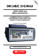

DM-14B & DM-14C User’s Guide
7
volume of the keys’ beep sound. To exit CONFIG. MENU press ESCAPE/MEAS. Please avoid using the
cancellation menu of the memory banks until you are confident with the use of the meter.
13) Now let us take a look at the SPECIAL MENU (see page 13). To reach this menu, press the SPECIAL key once:
• SELF TEST: this is used if there are faults to see which parts are not communicating and to obtain the various
data information needed to inform the ROVER service (including the SW and FW versions and the instrument’s
serial number SN).
• A/V MONITOR: forces the video/audio input from the Scart socket (even without 12 V on the relevant PIN).
• TEST MONITOR: generates a test pattern (which can be used to test TV DC installations).
The video is available on pin 15 of the SCART socket.
• RF/IF INPUT SEL: selects the meter’s RF IN, either RF or IF: (38.0 / 38.9 / 45.75 MHz)
• VOLTMETER: measures the AC/DC voltage present at the RF connector.
• REFLECTOMETER: to measure the distance of a short circuit, interruption or mismatching in coaxial cables.
• AUTO SCAN (TV): to scan a channel plan for the search of analog or digital (COFDM) TV channels and
the relative automatic memorization inside the plan.
• FILE MANAGER: for file management (canalizations, plans, loggers, etc…) in the memory.
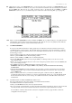
14) BARS SCAN FUNCTION: This activates the bar chart graphics representation. In a display it is possible to see the
level/power of all the TV programmes stored in a plan. This function is useful for tilt adjustments and equalizations
in cable distribution networks and headends.
15) NAVIGATION IN MEASUREMENT MODE (from pages 17 to 35) the various parameters can be quickly
changed using the direct function keys. We remind you once again that in this case the program number disappears.
At this point you have two options:
a) Press the programme key and select the same or another program number.
b) Press MEMORY and store the selected parameters previously modified (see page 14).
16) NAVIGATION IN SPECTRUM MODE (from pages 36 to 47): the various parameters can be navigated using the
arrow and ENTER keys and are the same as those used by other more expensive, professional spectrum analysers.
The measurement dynamic range and the spectrum speed of this instrument are by far the best in this category and
despite everything, AUTOMATIC mode is very easy to use. Let’s take a look at some of the main functions:
• Reference level: this is the level of the reference line (the first line at the top of the grid) is adjusted
automatically to the carrier with the highest level inside the SPAN. When the SPAN varies, press SPECTRUM
twice to up-date and obviously you can also manually adjust it using the UP & DOWN keys. (N.B. The ref.
level corresponds to the attenuator of previous instruments). Remember that each time you change mode or turn
on the instrument again the ref. level automatically returns to the top of the ref. level (also in manual mode).
• Marker Frequency: shows the marker frequency (vertical dotted line); automatically in digital and analogue
SAT and it always positions in the centre of the carrier, whereas in analogue TV it always positions on the video
carrier. N.B.: The FREQUENCY MARKER is basically the meter's frequency tuning; in fact the marker can be
moved on the various carriers and when you go to MEAS mode you are automatically positioned on the same
frequency. If this frequency is exactly the same as one of the memorised channels, you will also see the relevant
channel, otherwise the display shows 3 lines (to remind you that something has been changed). Important: the
cursor also navigates outside the SPAN's limits, to the far left (start), to the far right (stop). If you release the
arrow keys every now and then, the tuned carriers are shown (the ones that were previously out of the SPAN
range). Naturally if you change from SPECT to MEAS, you can go directly to the tuned carrier/channel. For
easier viewing in Analogue TV and with 10 MHz SPAN, the centre of the channel will be positioned in the
centre of the display, whereas with the rest of the SPAN the marker is positioned in the display's centre.
• Marker level: shows the level of the signal measured by the marker (horizontal dotted line with crosses) and is
connected to the marker frequency position.
(N.B. When the MRK level line is on the highest carrier, it may be confused with the REF LEVEL line, the
highest line on the grid and become invisible).
• SPAN: this always shows the total bandwidth in MHz between the extreme left and extreme right of the display
(if you divide the value by 10 you can obtain the value of each square division).
• dB/div: shows the value in dB between each division of the horizontal grid. This is very helpful if you require a
wide dynamic range, e.g. 10 dB/div., to see noise AND interferences or a high resolution, 1 dB/div. For very
accurate SAT dish pointing both in SAT & TV. In this condition you can easily appreciate variations in dB
decimals.
• MODE: it shows which mode the instrument is working in (the various digital or analogue modulations, TV or
SAT etc.) and in SAT, you can also select the satellite dish pointing function; it automatically sets the spectrum
to easily point any satellite dish. To quit this function press ESCAPE/MEAS. MODE can also be used to select
the V.SAT function, providing a high resolution spectrum for V.SAT and SCPC installations.
May we remind you that when you press MENU you can also select:
• SPECTRUM: automatic or manual. If positioned on AUTOMATIC it always adjusts the SPAN and the dB/
so you can see the carrier, which is being examined.
• DEFINITION: high, medium, low. This increases the spectrum speed (to facilitate dish pointing).