
Service manual

3
SERVICE INSTRUCTIONS
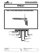
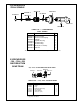
DISASSEMBLY
- GENERAL (All Models)
Clamp the handle in a soft-jawed vise and using a wrench
unscrew the quick change chuck (left hand threads). Un-
screw the clutch housing from gear case. Unscrew and
remove the gear case assembly from the handle. The motor
unit may now be removed from the backhead.
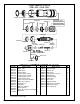
CLUTCH DISASSEMBLY
Clecomatic Clutch:
Unscrew (left hand threads) the adjustment nut 869123, and
remove the adjustment lock ring 869140. The torque spring,
bearing races 863455, thrust bearing 847104, ball retainer,
203573, and four (4) steel balls 842161, may now be
removed from the clutch spindle.
Washing the remaining spindle asembly in a solvent will aid
disassembly. Remove the ball retainer ring 203574, and ball
retainer plug 869149, from the clutch cam 203572. Rotate
the clutch spindle, to allow the thirteen (13) steel balls
842980, to drop out of the ball loading hole located in the
clutch cam. Separate the clutch spindle and clutch cam,
being careful not to lose the reset pin 869112, reset spring
203585, reset pin stop 869424, trip slide 203612, trip slide
reset spring 203613, and dowel pin 617226.
Quick Change Chuck
Removing retainer ring 833688, will release all parts in the
quick change chuck. The rest of the clutch disassembles the
same as finder clutch.
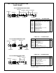
GEAR TRAIN DISASSEMBLY
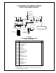
-104 Gear Train
Spiders should be removed from the rear of the gear case.
Remove the bearing retainer ring 619017 and press the
spider bearing 847595, out the front of the gear case. If
replacement of the idler gear pins is necessary, they should
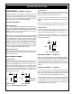
be pressed out the rear of the spider. If replacement of the
first reduction spider pinion 869132 is necessary, if should
be pressed out the front of the spider. See Figure 1 for
replacement dimensions.
2nd Red. Spider 1st Red. Spider
Fig. 1: -104 Gear Spider Gear Train:
-174 Gear Train
When pressing the spider assembly out of the rear of the
gear case 869162, be sure the idler gears 869163, are in line
with the pockets machined in the gear case.
Press the idler gear pins 833862, out the rear of the spider
869155, for inspection of the idler gear pins and idler gears
869163.
Remove the bearing retainer ring 619017, and press the
front spider bearing 847595, out the front of the gear case.
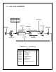
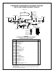
-254 Gear Train:
Press the spider assembly out the rear of the gear case.
Remove the bearing retainer ring 619017, and press the
front spider bearing 847595, out the front of the gear case.
If replacement of the idler gear pins, is necessary, they
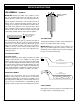
should be pressed out the rear of the spider. See Figure 2 for
replacement pin height.
Fig. 2: -254 Gear Spider
MOTOR DISASSEMBLY — (All Models)
Slip the front bearing 842768, and front bearing plate 203641,
off the front of the rotor and remove the cylinder 203504, and
four (4) rotor blades 203615. Set the rear bearing plate on
the vise jaws with the rotor hanging down. Use a 3/16"
(4.8mm) punch to drive the rotor out of the rear rotor bearing
842768.
HANDLE DISASSEMBLY — (All Models)
For inspection or replacement of the throttle valve or related
parts, rol down the grip sleeve and drive trigger bushing
retainer pin out and removing bushing. Shut off valve and
seal can be removed by removing 203559 valve cap.
The reversing valve may be removed by first unscrewing the
reversing valve screw out of the reversing valve knob. Then
reversing valve may be removed from the handle. On
reassembly make sure the reversing valve screw aligns with
the threaded hole in reversing valve.
.225
(5.72mm)
.220
(5.59mm)
Front
Rear
Pinion should be
pressed in flush
to .005 (1.27mm)
below surface.
.222
(5.64mm)
.218
(5.54mm)
RearFront
.225
(5.72mm)
.220
(5.59mm)
Front Rear