
Owner`s manual
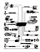

Sec on dary Ig ni tion or Heater/AC Wire
More and more vehicles are being manufactured with two ignition or two heater/AC wires in order to split up the power
requirements of the temperature control system, on-board computers, fuel delivery system, electroni c transmisssion control, etc. If
you are working on such a vehicle, you will find two wires that both test as ignition lines or two wires that supply the heater/AC.
Connect the ORANGE/GRAY wire to the 2nd ignition line and the GRAY/ORANGE to the second heater/AC l ine.
Ac ces sory Line Con nec tion
Most vehicles have a separate accessory line to power the radio, electric windows, demister, etc.
1.Turn the ve hi cle’s ra dio ON and ro tate the ig ni tion key to ACC. The ra dio should turn on.
2.Lo cate the one wire that car ries +12V only when the ig ni tion key is in the ACC and ON po si tions, but 0V while the key is in the
START po si tion.
3.Cut this wire.
4.Start the en gine. The ra dio should not op er ate.
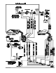
5. Con nect the OR ANGE wire to the ac ces sory wire as shown on page 3.
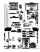
Auto matic Trans mis sion
1. If the vehicle has an automatic transmission, connect the IntelliStart 4 BLACK/GREEN wire to ground .
CON NECT THE INTELLISTART 4 BLACK/GREEN WIRE TO GROUND ONLY IF THE VE HI CLE HAS AN AUTO MATIC
TRANS MIS SION! AN IN COR RECT CON NEC TION CAN CAUSE SE VERE IN JURY OR DEATH.
2. Ver ify that the re verse lights il lu mi nate when the trans mis sion is put in re verse.
3.Find the one wire in the kick panel that reads +12V only when the transmission is in reverse.
4. Con nect the IntelliStart 4 BLUE/GREEN wire to this wire as shown on page 7.
Man ual Trans mis sion
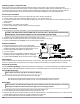
1.Find two wires going in to a connector on the clutch pedal.
2. Unplug the clutch pedal connector, then try to start the vehicle while
pressing the clutch pedal. The engine should neither start nor crank.
3. Connect the BLUE/ORANGE wire to an optional relay.
4. Turn on the ignition.
5.Find the one wire near the emergency brake that carries +12V when
the emergency brake is engaged and 0V when it is disengaged.
6.Con nect the BLUE/GREEN wire to this wire as shown on page 7.
Die sel En gines
There are two meth ods for interfacing with die sel en gines: use the “Wait-to-Start” light which w ill trigger the starter when the light
turns off, or use the built-in 20 sec ond timer which cranks the en gine 20 sec onds af ter the rem ote start command is received.
Using the 20 second delay:
Using the Installer-Programming, change the engine setting to “Diesel Engine,” or use the CliffordWizard Pro installation software to
program the system. The CliffordWizard Pro will also allow you to customize the delay to an interva l other than 20 seconds.
Using the Wait-to-Start light:
Note: Skip this sec tion if us ing the 20 sec ond de lay method.
Check the polarity of the two wires at the bulb of the Wait-to-Start light.
o If the po lar ity is posi tive when the light turns off, con nect the BLUE/YEL LOW wire to this wir e.
o If the po lar ity is nega tive when the light turns off, con nect the BLUE/BLACK wire to this wire.
Brake Lights
The AvantGuard 4 monitors the brake light to prevent an unauthorized driver from driving the car. The brake
light input wire MUST be connected and brake light must be in working condition.
1. Turn the ignition ON and press the brake pedal to make sure the brake light turns on.
2.Connect the black lead of the voltmeter to ground and set the dial to DC volt.
3.Probe one of the two wires at the brake pedal switch with the voltmeter red lead. The voltmeter sh ould read +12V when you press
the brake pedal; 0 volts when released. If no signal is detected, try the other wire.
4.Connect the BLUE/WHITE wire to the brake light wire as shown on page 7.
10 Avant Guard 4/699