
Owner`s manual
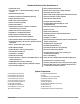
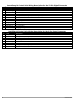
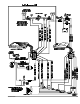
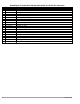
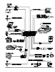
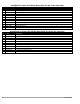
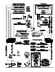
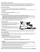

AvantGuard 4 Control Unit: Wir ing De scrip tion for the 24- Pin Connector
Pin Color Con nects to
2 Red/Black Optional OmniSensor output (+5v)
3 White/Blue Proximity Sensor input
4 Violet LED output (+)
6 Red Tilt Sensor and siren supply (+12v)
7 Blue/Yellow windshield wiper input (-)
8 Gray/Yellow Trunk trigger switch input (-)
9 Black Ground for the siren, sensors, LED and valet switch
10 Black Ground
11 White Valet switch input
12 Gray Twinlead Light sensor input
13 Gray/Violet Auxilliary A output
14 Gray/Blue Auxilliary B output
15 Gray/Red Auxilliary C output
16 White/Blue Optional Omnisensor input
17 Yellow Optional airhorns output (2 amps) (-)
18 Red Battery positive input (5-amp fuse)
20 Green Tilt sensor and armed signal output (-)
22 Gray Twinlead Light sensor input
23 White/Black Hood trigger switch input
24 Orange Optional sensor input
4 Avant Guard 4/699