
Owner`s manual
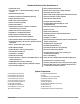
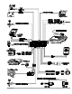

IntelliStart 4 Control Unit: Wir ing Description for the 12- Pin Connector
Pin Color Con nects to
1 Black/Green Ground for automatic transmission mode
2 Violet/White Pulse out (negative) after remote start for door lock upon remote start
3 White/Black Hood input (-)
4 White/Violet Pulse out (negative) before remote start for factory disarm prior to remote start
5 Red Battery positive (5-amp fuse)
6 Blue/Orange Out (negative) when remotely started for additional ignition relay or factory disarm
7 Black ground
8 Blue/Black Negative switching “Wait to Start” bulb for diesel engine installations
9 Blue/Yellow Positive switching “Wait to Start” bulb for diesel engine installations
10 Blue/Green Blankic transmission, connect to reverse light / manual, connect to emergency brake light
11 Blue/White Brake light input (+)
12 Black/Gray RPM Input
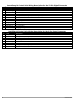
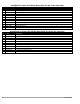
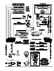
AvantGuard 4 Con trol Unit: Wir ing Description for the 14- Pin Con nec tor
Pin Color Con nects to
2 Blue/White Brake light input/output
5 Blue windshield wiper input (+)
6 White/Orange Door unlock common
7 White/Green Door lock common
8 Red/White Battery positive (20-amp fuse) input
9 Brown/Red Interior Light Supply (+ or -)
10 Gray Door trigger (+ or -)
11 Red/Orange Door unlock normally open
12 Red/Green Door lock normally open
13 Gray/Green Door unlock normally closed
14 Gray/Orange Door lock normally closed
6 Avant Guard 4/699