
Owner`s manual
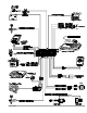

Passenger Compartment Connections
Control Unit and Extended Range Receiver
The AvantGuard 4 con trol unit must be in stalled in side the ve hi cle. Un der no cir cum stances should the unit be
in stalled un der the hood or other simi larly hos tile en vi ron ment.
1.Select an area behind the dash to mount the control unit using wire ties, but do not permanently af fix it until all wiring and testing
is complete.
2. Plug the extended range receiver in to the control unit. Mount the extended range receiver away fr om the control unit and run
the antenna either up the window pillar and affix it to the windshield, or under the dash, away fro m metal. The position and
location of the receiver will effect remote control range. Do not fold the excess cable or antenna wire. Do not make hard, sharp bends.
Door Trigger/Interior Light Supply
Please refer to the Door Trigger/Interior Light Supply section in this binder for information on polarity testing and connections.
Central Door Locking System
Please refer to the Door Locks section in this binder for information on circuit types and connections.
LED Status Indicator
Select a prominent location on the dash or console visible through all windows. Discuss placement w ith the owner.
1. Verify there is adequate space to accommodate the LED, then drill a 5/16” (8mm) hole and route the wires through it.
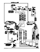
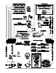
2. Mate the LED connectors to the VIOLET and BLACK wire connectors as shown in the diagram on page 5.
3.Press the LED into place.
PlainView 2 Coded Valet Switch
1. Discuss placement of the switch with the vehicle owner. It should be mounted in a location that is easily accessible to the driver of
the vehicle.
2.Verify there is adequate space behind the selected location to accommodate the switch.
3.Drill a 5/16” (8mm) mounting hole, then insert the wires through the hole and mount the switch.
4. Mate the switch’s locking connectors to the WHITE and BLACK locking connector as shown on page 5.
Remotely Adjustable Dual-Zone Proximity Sensor 4
This efficient new-generation proprietary radar sensor is immune to the wind and temperature variat ions that cause ultrasonic
sensors to false alarm. The sensor must be mounted onto a metal surface and face outward into the p assenger compartment and
should be positioned as close as possible to the center of the passenger compartment. Suggested mou nting locations include within
the center console, behind the dash, under the carpeting of the central hump or even in the headlin ing. When selecting a location,
keep in mind that metal as well as metallic paint, metallic-colored plastic and metal-laced window tint material will interfere with the
radar field. Be certain not to mount it in a location under the console over which the vehicle owne r may store coins, CDs or cassettes
(iron-oxide tape). The radar waves of the sensor will pass through nonmetallic materials such as plastic, fabric and carpet.
1.Temporarily affix the sensor where it will be mounted, but do not yet permanently mount it until af ter adjusting and testing
sensitivity (the sensor may need to be relocated, so do not permanently secure it until it has been thoroughly tested).
2. Plug the connector with the BLACK, WHITE/BLUE and RED/BLACK wires into the sensor, then secure the wires with a cable tie.
Digital Tilt/Motion Sensor
Find a solid, firm horizontal surface within the passenger compartment (such as under the seat) and thoroughly prep the area for
mounting. Do not mount the sensor on the transmission hump, rapid heat buildup can affect sensitivi ty. The unit is mounted with
the supplied double-sided adhesive material, so the mounting area must be very clean.
1.Mount the unit onto a clean, horizontal surface using the supplied double-sided adhesive material.
2.Join the connector from the Digital Tilt/Motion Sensor with the connector with the GREEN, ORANGE, R ED and BLACK wires
as shown on page 5, then secure the wires with a cable tie.
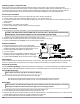
NOTE: The Digital Tilt/Motion Sensor will become active 10 seconds after arming the system. Some v ehicles,
such as Range Rovers, lower after the ignition is turned OFF and require more time before the senso r
activates. To extend this time delay, cut the sensor wireloop — this will provide a two-minute del ay.
8 Avant Guard 4/699