
Owner`s manual
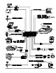

Parking Lights
See the Door Trigger & Parking Lights sections in this binder.
NightVision Light Sensor
1. Mount the Light Sensor in a discreet location on the dashboard. The light sensor must be positione d in such a way that the light
“eye” can detect light coming through the windshield.
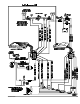
2.Connect the BLACK twin lead con nec tor from the light sen sor to the GRAY twin lead from the 24- p in con nec tor.
Windshield Wipers
1. Using a DVM, test the wiper switch output line going to the motor. If the polarity is positive whe n you turn the windshield wipers
on, connect the BLUE wire to the line between the wiper motor and the wiper switch. If the polarit y is negative, connect the
BLUE/YELLOW wire to the line between the wiper motor and the wiper switch as shown on page 5.
2.Insulate or tape the unused wire.
Headlights
1.Locate the wire at the headlight switch that changes voltage when the headlights are turned on.
2.Connect the RED/BLACK wire to this line.
3.If the line indicates positive while the headlights are on, connect the RED/WHITE wire to the batte ry positive post via a 30-amp
fuse. If the line indicates negative while the headlights are on, connect the RED/WHITE wire to gr ound.
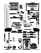
Starter and Ignition Connections
Im mo bi li za tion Cir cuits
1.Locate the ignition switch wireloom under the dash and use a voltmeter to locate the one wire that carries +12V throughout
BOTH the cranking AND engine running cycles, and 0 volts when the ignition is off.
You may find two wires in the steering column wireloom that test this way. If so, see the Secondar y Ignition or
Heater/AC wire section below.
2.Start the engine, then cut the ignition wire. The engine should stop running.
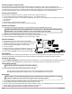
3. As shown on page 3, connect the WHITE/BROWN wire of the AvantGuard 4 to the key side of the cut ignition line.
4.Connect the GREEN/BLUE wire of the AvantGuard 4 and the GREEN/BLUE wire of the IntelliStart 4 to the engine side of the
cut ignition line.
Starter Con nec tion
You MUST con nect the starter wires be fore the neu tral safety switch, oth er wise the engine coul d be started
while in gear. Also note that the starter cir cuit may have very high cur rent. Be cer tain that both the
WHITE/GREEN and WHITE/BLUE wires are sol idly con nected. For maxi mum de pend abil ity, sol der a nd shrink
tube these con nec tions.
1.Use a voltmeter to locate the one wire that carries +12V during the cranking cycle ONLY. Cut this wire, then try to start the
engine. It should not crank.
2.Con nect the WHITE/GREEN of the AvantGuard 4 wire to the key side of the cut starter line.
3.Connect the WHITE/BLUE wire of the AvantGuard 4 and the WHITE/BLUE wire of the IntelliStart 4 to the starter side of the
cut starter line.
Heater/Air Con di tioner Con nec tion
1.Turn the vehicle’s heater/AC switch on and rotate the ignition key toward START one increment at a time. Observe at which
position the blower turns on.
2.Turn the engine OFF.
3.Connect the voltmeter black lead to ground and set the dial to DC volt.
4.Locate the one wire that carries +12V only when the ignition key is at the position where the blower activates.
5.Cut the wire.
6.Start the engine. The blower should not operate.
7. Connect the GRAY wire to the heater/AC wire as shown on page 3.
Avant Guard 4/699 9