Installation Guide Concept 470 © 2006 Directed Electronics Vista, CA N919600 11-06
IMPORTANT! Please note that this manual was intended for US consumers and therefore includes American phrases or words. Bitwriter™, Code Hopping™, DEI®, Directed®, Doubleguard®, ESP™, FailSafe®, Ghost Switch™, Learn Routine™, Nite-Lite®, Nuisance Prevention Circuitry®, NPC®, Revenger®, Silent Mode™, Soft Chirp®, Stinger®, Valet®, Vehicle Recovery System®, VRS®, and Warn Away® are all Trademarks or Registered Trademarks of Directed Electronics, Inc., Vista, California.
contents warning! safety first . . . . . . . . . . .2 before beginning the installation 3 after the installation . . . . . . . . .3 arming . . . . . . . . . . . . . . . . . . .22 disarming . . . . . . . . . . . . . . . .22 system status chirps . . . . . . . . . . .23 transmitter functions . . . . . . . . . .4 standard configuration . . . . . . .4 remote siren silencing . . . . . . . . .23 primary harness wire connection system features programming . .
warning! safety first The following safety warnings must be observed at all times: z Due to the complexity of this system, installation of this product must only be performed by an authorized Clifford dealer. z When properly installed, this system can start the vehicle via a command signal from the remote control transmitter. Therefore, never operate the system in an area that does not have adequate ventilation.
OPERATION OF THE REMOTE START MODULE IF THE VEHICLE STARTS IN GEAR IS CONTRARY TO ITS INTENDED MODE OF OPERATION. OPERATING THE REMOTE START SYSTEM UNDER THESE CONDITIONS MAY RESULT IN PROPERTY DAMAGE OR PERSONAL INJURY. IMMEDIATELY CEASE THE USE OF THE UNIT AND REPAIR OR DISCONNECT THE INSTALLED REMOTE START MODULE. CLIFFORD WILL NOT BE HELD RESPONSIBLE OR PAY FOR INSTALLATION OR REINSTALLATION COSTS.
transmitter functions This system uses computer-based code learning to learn the transmitter buttons. This makes it possible to assign any transmitter button to any system function. The transmitter initially comes programmed with standard configuration, but may also be customized by an authorized dealer. The buttons in all of the instructions in this manual correspond to a standard configuration transmitter.
primary harness wire connection guide primary harness wiring diagram H1/1 ___ BLACK H1/2 ___ BROWN H1/3 ___ GRAY H1/4 ___ EMPTY H1/5 ___ GREEN/WHITE H1/6 ___ WHITE/BLUE H1/7 ___ BLUE (-) Trunk Trigger Input - Zone 5 H1/8 ___ VIOLET (+) Door Trigger Input - Zone 4 H1/9 ___ GREEN (-) Door Trigger Input - Zone 4 H1/10 ___ RED (+) 12V Constant H1/11 ___ BROWN Speaker Output 2 H1/12 ___ WHITE/RED H1/13 ___ WHITE Light Flash Output H1/14 ___ WHITE Light Flash Output H1/15 ___ B
primary harness wiring guide This guide describes in detail the connection of each wire. Also included are possible applications of each wire. This system was designed with the ultimate in flexibility and security in mind. Many of the wires have more than one possible function. Please read the instructions carefully to ensure a thorough understanding of this unit and how it operates.
h1/5 green/white (-) normally closed zone 6 This wire will trigger the alarm if it looses its normally closed ground. Remove this wire from the ground wire and attach it to a normally grounded item you wish to protect such as the back of your stereo. h1/6 white/blue (-) accessory b output (200mA) This wire produces a 200mA output when activated by the remote control and can be used to operate a variety of accessories. All accessory outputs can be programmed to different types of outputs.
h1/12 white/red light flash input This wire is the input for the on-board dual light flash relay. If the vehicle has positive parking light activation wires, connect this wire to a constant (+) 12V source that is fused at 15A or higher (be sure to use the supplied fuse holder and a 15 amp fuse). If the vehicle parking light activation wire is negative, connect this wire to a chassis ground location.
secondary harness wire connection guide secondary harness wiring diagram H2/1 ___ YELLOW/WHITE H2/2 ___ EMPTY H2/3 ___ BLACK/WHITE Domelight Supervision Input (87) H2/4 ___ BLUE/WHITE Second Unlock Output (200 mA) H2/5 ___ EMPTY Not Used H2/6 ___ EMPTY Not Used (-) Horn Honk Output (200 mA) Not Used secondary harness wiring guide NOTE: For further description of the H2/1 to H2/6 wires, please refer to the Door Lock Harness Wire Connection Guide section.
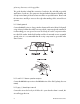
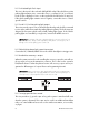
immobilizer harness wire connection guide immobilizer harness wiring Locate the ignition and starter wires using a multimeter. Cut the appropriate wire and attach the key side and car side wires to the corresponding wires on the four-pin immobilizer harness. NOTE: The diagram below shows the module side of the connector (looking into the female pins).
been restored to the module. NOTE: In order for the system to bypass the immobilizer with the jumper in place, the unit must have ground on the 18-pin harness.
type A: positive (+) 12-volt pulse The system can control Type A door locks directly, with no additional parts. The switch will have three wires on it; one will test (+)12 volt constantly. The others will alternately pulse (+)12 volt when the switch is pressed to the lock or unlock position. If you cannot get to the switch, and you find a set of wires that pulse (+)12 volt alternately on lock and unlock, make sure that it is not a Type C direct-wire system.
type B: negative (-) pulse This system is common in many Toyotas, Nissans, Hondas, and Saturns, as well as Fords with keyless entry systems (some other Fords also use Type B). Most European Ford vehicles with (-) negative pulse locking are high current so a 451M or 2 relays need to be used. The switch will have three wires on it, and one wire will test ground all the time.
type C: reversing polarity Interfacing with a reversing polarity system requires either two relays or one 451M (not included). It is critical to identify the proper wires and locate the master switch to interface the door locks properly. Locate wires that show voltage on lock and unlock. Cut one of the suspected wires and check operation of the locks from both switches.
type D: after-market actuators In order for this system to control one or more after-market actuators, a 451M or two relays (optional) are required. Vehicles without factory power door locks require the installation of one actuator per door. This requires mounting the door lock actuator inside the door. Other vehicles may only require one actuator installed in the driver's door if all door locks are operated when the driver's lock is used. The fuse used on 12 volt inputs should be 7.
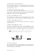
type E: mercedes-benz and audi (1985 & newer) Type E door locks are controlled by an electrically activated vacuum pump. Some Mercedes and Audis use a Type D system. Test by locking doors from the passenger key cylinder. If all the doors lock, the vehicle's door lock system can be controlled with just two relays (optional). The control wire can be found in either kick panel and will show (+)12 volt when doors are unlocked and (-) ground when doors are locked. To interface see diagram below.
type F: one-wire system Type F door locks usually require a negative pulse to unlock and cutting the wire to lock the door. In some vehicles, these functions are reversed. Type F door locks are found in late-model Nissan Sentras, some Nissan 240SX, and Nissan 300ZX 1992up. They are also found in some Mazda MPVs, some Mitsubishis, and Lotus.
type G: positive (+) multiplex The door lock switch or door key cylinder may contain either one or two resistors. When interfacing with this type of door lock system, two relays or a 451M must be used. Single-Resistor Type If one resistor is used in the door lock switch/key cylinder, the wire will pulse (+)12 volt in one direction and less than (+)12 volt when operated in the opposite direction.
type H: negative (-) multiplex The door lock switch or door key cylinder may contain either one or two resistors. When interfacing with this type of door lock system, two relays or a 451M must be used. Single-Resistor Type If one resistor is used in the door lock switch/key cylinder, the wire will pulse ground in one direction and resistance to ground when operated in the opposite direction.
peripheral plug-in harnesses super bright blue led, 2-pin white plug The super bright LED operates at (+) 2V DC. Make sure the LED wires are not shorted to ground as the LED will be damaged. Multiple LEDs can be used, but they must be wired in series. The LED can be top-mounted or flush-mounted. If top-loading the LED with a bezel, the LED fits into a 5/16-inch mounting hole. If flush-mounting the LED from the back of a panel, drill a mounting hole using a 17/64-inch drill bit.
blue and orange wires, zone 3 zone 8 These wires are multiplex inputs. If a (-) input of less than 0.8 seconds is supplied to either wire, the Warning Zone response will occur. A (-) input of longer than 0.8 seconds to either wire will initiate the triggered sequence and report Zone 3 or Zone 8. NOTE: For mounting and adjustment of sensors, please refer to the Mux Sensors section of this guide.
and plug the cable into the control module. arming/disarming diagnostics The systems microprocessor monitors and reports all active and violated zones when arming and disarming the system. arming Zones that are triggered at the time the system is armed are reported by an additional set of status chirps called Malfunction AutoBypass. The specific zone bypassed is then reported by the LED. For more zone information, refer to Table of Zones section of this guide.
system status chirps Action No. of Chirps Description Arm 2 System armed. Arm 4 System armed with hood or trunk bypass zones 5 and 6. Arm 2 (5-second pause) 4 System armed with door bypass zone 4 Arm 2 (10-second pause) 4 System armed with sensor active and bypassed zones 1, 3, and 8. Disarm 1 System disarmed.
table of zones When using the diagnostic functions, use the Table of Zones to see which input has triggered the system. It is also helpful in deciding which input to use when connecting optional sensors and switches. LED Flashes Trigger type Input description NOTE: The Warning Zone response does not report on the LED.
Be sure to document changes by taking note of all feature changes made in programming mode. To enter the User Selectable Features programming: 1. Ignition on - Turn the ignition to the run position or start the engine. 2. Enter PIN - Enter the factory preset PIN code of 2 by pressing PlainView 2 Valet switch twice, then once. on the NOTE: If the factory preset PIN has been changed, the new PIN must be entered. 3.
user selectable features Then Press First Press Add new remote (autolearn) Set PIN code (default = 2) New remote learn arm/disarm only Auto (passive) arm on/off Select siren sounds New remote learn accessory A channel Chirps on/off/quiet FACT II on/off New remote learn accessory B channel Auto lock ignition/off/rpm Remote valet on/off New remote learn silent mode Auto unlock ignition/off Entry delay on/off New remote learn remote valet Auto (passive) arm and lock on/off Siren duration 30/6
auto lock - off/ignition/rpm z Off: The doors will not lock automatically. z Ignition: The doors will automatically lock three seconds after the ignition is turned on unless a door is open at that time. z Rpm: The doors will lock when the system sees the engine reach a preprogrammed RPM. The H1/4 VIOLET/BLACK or Intellistart must be connected.
within a one hour period. remote valet - off/on z Off: The alarm can not be put into valet mode with the remote control. z On: The alarm can be put into valet mode with the remote control. entry delay - off/on z Off: There is no entry delay when the system has passively armed. The system will trigger instantly when a door is opened.
z The remote control channel programmed into this feature will arm/disarm the system only. NOTE: When programming a new remote control to custom configuration a channel must first be programmed to this feature before programming the remaining channels. accessory a output z The transmitter channel programmed into this feature will activate the accessory output. accessory b output z The transmitter channel programmed into this feature will activate the accessory output.
installer selectable features To enter the Installer Selectable Features grid follow the instructions for the User Selectable Features with the exception of step 3. Perform step 3 as described below to enter the Installer Selectable Features grid. Hold/Chirp/Release - After entering the PIN code, press and hold until the siren chirps once. Continue holding for approximately 10 seconds until the siren chirps three times, then release the button.
installer selectable features descriptions - column one lock pulse single/double z Single: One door lock pulse will be output when the system arms. z Double: Two door lock pulses will be output when the system arms. unlock pulse single/double z Single: One door unlock pulse will be output when the system disarms. z Double: Two door unlock pulses will be output when the system disarms. lock pulse duration 0.8/3.5 sec z 0.8 seconds: The door lock pulses will be 800 milliseconds in length. z 3.
z Latched (ignition reset): The output on/off controlled by button(s) controlling accessory if on, will turn off when the ignition is turned on. accessory output b programming The auxiliary accessory output wire (WHITE/BLUE) can be programmed for several different types of outputs. z P1 0.8 seconds: The pulsed output is disabled with the ignition on or the alarm armed. z P2 0.8 seconds: The pulsed output will operate any time. z Timed: The length of output duration set.
installer selectable features descriptions - column three rpm programming z Programs the tachometer input for the BlackJax and door locks. For more information, see programming note #4. engine type petrol/diesel z This feature applies only if IntelliStart 4 is installed. z Petrol: The IntelliStart will crank the engine three seconds after the ignition is turned on or after input on the wait-to-start wires ceases.
programming notes Note #1: Adding a new transmitter in auto-learn configuration z Press the arm/disarm button of the remote control; the siren will chirp once. Note #2: Adding a new transmitter in custom-configuration z For the arm/disarm channel, transmit the channel of the new three or five button transmitter that you want to control that feature; the siren will then chirp once. z For the rest of the channels, press the desired button on the remote to do the specified feature.
z Programming Procedure 1. Enter the feature location in the user-selectable programming grid. 2. Immediately press and release 3. Select each digit by pressing of the PlainView 2 Valet switch. 1-9 times, and then press the number into the system. To enter a zero, press z only. To program a PIN code of 1032: 1. Press and release once and 3. Press and release once. You will not hear a chirp after programming 5. 6. 4. 5. 6. z to enter once. You will hear one chirp. a zero.
NOTE: The timer max setting is 255 seconds. z Accessory channel B can be programmed to auto-activate with the arm command of the transmitter, the disarm command of the transmitter, or both. Auto-activate can also be turned off and activate as a normal addition accessory channel output. accessory output b timer duration z Start Timer: Press the arm/disarm button; the siren will chirp to signal the start of the timer duration setting.
smart power up II The Smart Power Up II feature ensures that when the security system is powered back up after being disconnected, the system will resume the same state it was in before power was lost. For example, if power is disconnected during a full trigger sequence, the system will still be in the full trigger sequence when power is reconnected to the unit. If power is disconnected while the unit is disarmed, it will still be disarmed when power is restored. remote control sensor disable 1.
shock sensor The 504C dual zone magnetic resonance shock sensor provides a warning trigger for lighter impacts to the vehicle as well as a full trigger for heavy impacts. mounting the shock sensor Mount the 504C sensor with wire ties or double-sided tape. Air ducts or wiring harnesses work well for mounting, although it is best to avoid harnesses containing lighting circuits.
z Arm the alarm and then disarm the alarm. z Turn the ignition on and enter the system valet/PIN code. one-time valet feature This feature allows the system to be put in valet mode only until the next time the ignition is turned off. ON: Valet mode will be exited every time the ignition is turned on.
troubleshooting Sensors do not trigger the alarm. z Has the FACT II system been triggered? To check this, turn the ignition key on and off to clear the FACT II from memory, and then retest the shock sensor. For a detailed description of FACT II, see the FACT II: False Alarm Control Technology section of this guide. Closing the door triggers the system, but opening the door does not. z Have you correctly identified the type of door switch system? This happens often when the wrong door input has been used.
© 2006 directed electronics GREEN/WHITE - (-) Normally Closed Zone 6 EMPTY WHITE/BLUE - (-) Accessory B Output (200mA) BLUE - (-) Trunk Trigger Input - Zone 5 VIOLET - (+) Door Trigger Input - Zone 4 BROWN - Speaker Output 1 GRAY - (-) Hood Trigger Input Zone 6 GREEN - (-) Door Trigger Input - Zone 4 18-Pin Primary Harness EMPTY ORANGE - Ground When Armed Output (-) 500mA RED/WHITE - (-) Accessory Output A (200mA) BLACK/WHITE - Domelight Supervision Output 30 BLACK - Ground RED - 12V Input B
42 © 2006 directed electronics YELLOW/WHITE - (-) Horn Honk Output (200mA) EMPTY BLACK/WHITE - Domelight Supervision Input (87) 6-Pin Secondary Harness BLUE/WHITE - Second Unlock Output (200mA) EMPTY EMPTY
Concept 470 © 2006 directed electronics 43