Downloaded from: http://www.guardianalarms.
Table of Contents Standard Features of the ACE 7500 . . . . . . . . . . . . . . . . . . . . . . . . . 2 Important Information . . . . . . . . . . . . . . . . . . . . . . . . . . . . . . . . 3 Required Installation Tools . . . . . . . . . . . . . . . . . . . . . . . . . . . . . 3 System Components . . . . . . . . . . . . . . . . . . . . . . . . . . . . . . . . . 3 Wiring Diagram - 12-pin Connector . . . . . . . . . . . . . . . . . . . . . . . . . 4 Wiring Diagram - 24-pin Connector . . . . . . . . . . . . .
Standard Features of the ACE 7500 o Lifetime Warranty o Eight-Event TotalRecall™ o His & Hers Remote Controls o ACG™ 2 (Anti-CodeGrabbing™) o Prewired LED, Sensor, Extended Range Receiver and PlainView 2 Switch Connectors o Extended Range Receiver o Dual-Mode “Chirp” Silencing o Remote Engine Starting with AutoStart o Remote Siren Silencing o Smart Remote Trunk Release o Works with Automatic or Manual Transmissions o Built-In Dual Parking Light Flasher with Onboard Relay o Works with Diesel or Gas
Important Information 1. DO NOT disconnect the battery cables! Make battery connections by removing the lug nuts from the battery clamps without detaching the clamp itself. 2. Turn off the interior lights or remove the dome light fuse before starting the installation; otherwise, leaving the door(s) open during installation will drain the battery. 3. Use a voltmeter.
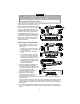
Wiring Description for the 12-Pin Connector Pin 1 2 3 4 5 6 7 8 9 10 11 12 Wire Color Red Gray Green/Blue Red Red Brown White/Green Orange Brown White/Blue Not used White/Brown Connects to Battery (+) with 30-amp fuse Heater/AC output Coil side - ignition (+) (and relay shown if manual transmission) Battery (+) with 30-amp fuse Battery (+) with 20-amp fuse Parking light output (+) Key side - starter input (+) Accessory output Parking light output (+) Starter side - starter output (+) Not used Key side - i
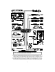
Control Unit and Extended Range Receiver The ACE 7500 control unit must be installed inside the vehicle, never under the hood or other similarly hostile environment. 1. Select a mounting area, but do not affix the control unit until wiring and testing is complete. 2. Plug the 18” CliffNet DataPort Extension Cable into the control unit. Make sure the receptacle end will be accessible after the dash has been put back. This eases later service. 3.
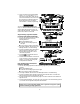
Wiring Description for the 24-Pin Connector Pin Wire Color 1 2 3 4 5 6 7 8 9 10 11 12 13 14 15 16 17 18 19 20 21 22 23 24 White/Blue White/Violet Black/Gray Blue/Green White Orange White/Black Gray/Yellow Blue/White Black Red Black Gray/Green Green Violet/White Gray/Violet Gray/Orange Red Violet Yellow Blue/Black Brown/Red Gray Blue/Orange Connects to Remotely Adjustable Dual-Zone Piezo Sensor input Pulse out before remote start (-) and upon disarming RPM input Reverse light input (+) Valet switch input
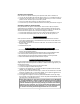
Accessory Line Connection Most vehicles have a separate accessory line to power the radio, electric windows, etc. 1. Turn on the vehicle’s radio and rotate the ignition key to ACC. The radio should turn on. 2. Locate the one wire that carries +12V only when the ignition key is in the ACC and ON positions, but 0V while the key is in the START position. 3. Cut this wire, then start the engine. The radio should not operate. 4. Connect the 12-pin connector’s ORANGE wire to the accessory wire as shown on page 4.
Door Locks WARNING: If the power door locks do not operate properly when the system is armed and disarmed, DO NOT USE THE VEHICLE’S DOOR LOCK SWITCH! Permanent damage to the control unit or to the car’s electrical system and lock servos will result. For assistance, call the Clifford Technical Support Hotline PRIOR to wiring the door locks.
6. The ACE 7500 can also provide double pulses (+ or -) for lock and/or (+ or -) unlock that is required by some vehicles (such as some Nissans, VWs, and Audis). Wire the door locks following the steps above and select the 2x lock and/or unlock feature in installer-programming. Parking Lights The ACE 7500 has built-in parking light relays. To determine whether the vehicle has single or dual parking light circuit(s), you must access the fuse panel. A single circuit has one fuse; a dual circuit has two.
Factory Theft Deterrent Bypass The wiring noted below is to disarm a vehicle’s factory system to permit remote starting. For more information on factory theft deterrent bypass, check your Clifford Tech Support Database, visit www.clifforddealer.com (USER NAME = roadshop PASSWORD = cliffg4) or call our toll-free Circuit City Technical Support Hotline or AutoFax at 1-877-CLIFF-G4. 1. The BLUE/ORANGE wire is a negative out whenever the vehicle is remotely started.
RPM Monitoring The ACE 7500 monitors RPM which is REQUIRED for the operation of the remote engine starting electronics as well as the anti-carjacking electronics and RPM-dependent AutoLock feature. After powering up the system, you must perform the MANDATORY RPM PROGRAMMING noted on page 13. Some newer vehicles do not have a conventional coil marked (+) and (–). In these instances, you will need to locate the tach wire: 1. Try to locate the distributor cap which all spark plug wires run in to.
Remotely Adjustable Dual-Zone Piezo Sensor Mount this sensor in the passenger compartment, not in the engine compartment. 1. Firmly mount the sensor near the base of the steering column (if the steering column has a rotating sleeve, firmly screw the sensor to the interior firewall, kick panel or trunk wall). 2. Mate the sensor to the connector with the BLACK, RED, and WHITE/BLUE wires. 3. After power-up, adjust the sensor as noted on page 15.
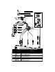
High Output Insignia Siren Mount the siren in the engine compartment away from hot or moving parts and where it cannot be reached from under the vehicle, preferable opposite the exhaust system. Point the siren down to avoid water collection (see the illustration). 1. You must firmly secure the siren to the engine bay firewall or a fender well using all three sheet metal screws supplied. 2.
Remote Control Operation The ACE 7500 comes with two ergonomically designed remote controls. Up to two more ACG 2 remote controls can be added to the ACE 7500 system (older Clifford ACG and non-ACG remotes are not compatible with the ACE 7500). If a remote control is ever lost or stolen, its identity can be erased from the system memory so that the missing remote control can never again be used to control the system.
Sensor Adjustment 1. Disarm the system with the master remote control. 2. On the master remote, press the LevelShift three times, then button 3. You will hear one chirp and the LED will turn on. 3. Test the primary (alarm) zone, by firmly “thumping” the top of the A-pillar (the area between the side windows near the roof) with the heel of your fist. If the impact is strong enough to trigger the primary zone, you will hear a siren chirp.
Programming the User-Selectable Features 1. Write down the column (across) number and row (down) number of the feature(s) you wish to program. 2. Turn the ignition to the “ON” position or start the engine. 3. Enter the factory preset valet/programming code of “2” by pressing the PlainView 2 Switch’s ✱ button two times, then press the blank button. 4.
n NOTE 1: Press button 1 on the 16-channel master remote, you will hear one chirp. Press button 1 again, you will hear two chirps. n NOTE 2: You will hear two chirps when all features are reset. Valet code and remote controls are not changed. n NOTE 3: When you hear two chirps, all remote controls will have been erased from the system memory. You must now add the new and/or existing remote controls to the system (i.e., Program each remote that will be used with the ACE 7500).
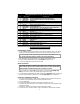
Table of Installer-Programmable Features (1 chirp = OFF, 2 chirps = ON) Feature Select Blank x 1 Blank x 2 Blank x 3 ✱x1 Single/Double Lock Pulse (1/2 chirps) NOT USED Door Ajar Warning /Delayed Courtesy Lights (1/2 chirps) ✱x2 Single/Double Unlock Pulse (1/2 chirps) ✱x3 Lock/Unlock Pulse 1 second/3 second (1/2 chirps) NOT USED NOT USED ✱x4 Pos/Neg Lock Polarity (1/2 chirps) NOT USED NOT USED ✱x5 Program RPM See Mandatory RPM Programming page 13) Diesel/Gas Engine* (1/2 chirps) AutoActi
NOTE: If none of the troubleshooting techniques described corrects the problem, perform the following diagnostics: nMake sure the fuses are in the fuseholders and check the power and ground connections. nVerify that the control unit connectors are properly inserted into the control unit. nVerify the ignition input and output wires are connected to the true ignition line instead of a +12V line. See the Starter and Ignition Connections section. nVerify that the transmitters are programmed correctly.
Step 7: Test BlackJax anti-carjacking feaure. Verify that this feature is on (it is factory set to off). To trigger BlackJax: 1. Shut all doors, then start the engine (be sure to press the brake pedal). 2. Wait. After 20 seconds, you’ll hear 5 chirps. Enter the PIN code (factory set to 2: ✱✱ blank). nNo chirps. Check the GRAY door trigger wire while the engine is running. Also verify that the brake input shows +12V when pressed, 0V when not pressed (engine running). 3.
Step 12: Test the door trigger circuit. Rearm, then use the key to unlock and open the driver’s door. nSiren sounds, parking lights flash repeatedly. This is the correct response, proceed to step 12. nSiren does not sound immediately. Make sure the door pin switches consistently show less than 1.5 volts if negative-switching or more than +11 volts if positive-switching. If not, then the door pin switch(es) are either defective or in need of cleaning. Step 13: Test the trunk trigger circuit.
Step 18a: Test the remote start function: AUTOMATIC TRANSMISSION. Program the system for automatic transmission (factory setting is for manual transmission). Make sure the gear lever is in PARK, the hood is closed, and the emergency brake is ON. nTest 1: Press button 4 on the master remote or the ✱ button on the companion remote. § Parking lights flash once and engine does not start. System has not be programmed for automatic transmission. See Installer-Programmable Features.