CoolLogic Control System Installation, Operation & Maintenance Manual
Table of Contents CoolLogic Control System Overview Appendix A. . . . . . . . . . . . . . . . . . . . . . . . . . . . . . . . . . . . . . . . . . 14 and Features. . . . . . . . . . . . . . . . . . . . . . . . . . . . . . . . . . . . . . . . . 3 Appendix B. . . . . . . . . . . . . . . . . . . . . . . . . . . . . . . . . . . . . . . . . . 15 CoolLogic Control System Optional Features . . . . . . . . . . . . . 7 Appendix C . . . . . . . . . . . . . . . . . . . . . . . . . . . . . . . . . . . . . . . . .
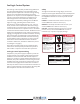
CoolLogic Control System The CoolLogic Control System provides leaving chilled and hot water liquid temperature control algorithms which maintain precise temperature control for cooling, heating, heat recovery and simultaneous heating and cooling applications. A compressor run time equalization sequence is given to ensure even distribution of compressor run time throughout the entire chiller bank.
Field Connections between Master Control Panel and Module Controller • 18 AWG, two conductor shielded cable (under 50 feet).
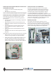
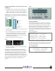
Configuring the Master Controller (I/O Pro 812u) for ARC156 Figure 4 1. Turn off the Master Controller’s (I/O Pro 812u) power 2. Using the rotary switches, set the Master Controller’s address. Set the Tens (10’s) switch to the tens digit of the address, and the Ones (1’s) switch to the ones digit. Example (Figure 1): If the Master Controller’s address is 01, point the arrow on the Tens (10’s) switch to 0 and the arrow on the Ones (1’s) switch to 1.
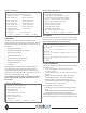
Figure 9: Service Menu (FN+7) Figure 7: Status Menu coollogic s ervice menu s etup fn 7 coollogic chiller status menu --> all module compr unload status f n5 [--> diagnostics manual mode] --> module size status / --> chiller oper st [--> all module compr unload status] fn5 --> mod1 comp1 data / --> mod1 comp2 data [--> all modules s ensor calibration menu] --> mod2 comp1 data / --> mod2 comp2 data [--> reset all module sens or oor alarms] --> mod3 comp1 data / --> mod3 comp2 data [--> reset c
Alarm Functions of the CoolLogic Control System High Pressure Cutout This requires resetting at both the module’s manual reset high pressure control switch and at the Master Control Panel’s software reset to resume operation (See page 5 (Setup Menu) for Alarm Menu display or press FN+3).
CoolLogic Control System Standard Features Chilled Water Flow Sensor or Switch Chilled Water Reset The Master Control Panel has an input for a differential pressure sensor or switch, which measures and displays pressure drops across the chilled water main headers. If the differential pressure drops below a predetermined setting for a fixed period of time after the chiller receives a “RUN” input signal, the chiller will not be allowed to run and a chilled water flow alarm condition is displayed.
CoolLogic Control System Optional Features Chilled Water Temperature Sensor Connections Chilled water temperature monitoring (entering and leaving) is a standard feature of the CoolLogic Control System. It is accomplished by using a factory supplied pair of sensors and sensor wells which are field installed into ½” weld-o-lets (field supplied and installed onto the main water headers) within 60” of the entering and leaving chilled water locations.
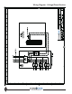
Wiring Diagram - Voltage/Phase Monitor 10 www.climacoolcorp.
Start Up and Warranty Form: CoolLogic Master Controller (FN+8) then “Main Water & Air Temp Limits” Page 1 of 2 Project Name: ___________________________ ________________________________________ Start-Up Date: ___________________________ Chiller # _______ Bank # _________ (FN+2) Evap Water In Low Limit……………………. Evap Water In Hi Limit…………….…………. Evap Water Out Low Limit…………………. Evap Water Out Hi Limit………….…………. Cond Water In Low Limit………….………… Cond Water In Hi Limit………….……..…….
Page 2 of 2 (FN+2) then “Heat Mode Setpoint Menu” Chiller # _______ Bank # _________ (FN+8) then “Master Input Chnls 8 & 11 Setup” Local Cond Water Out Setpoint………….. Min Cond Water Out Setpoint………….. Max Cond Water Out Setpoint ………….. Use Chn# 8 as Diff Pres Sensors? ………….. Use Hi Range Diff Press Sensors? ………….. Cond Water Min Dif Pr Flow Setpoint..….. Chill Water Min Dif Pr Flow Setpoint……… ________ ________ ________ ________ (FN+6) then “Avail. Sensor Menu Temp.
www.climacoolcorp.
Status User Access ClimaLogic Heirarchy for Screen Menus Module Size Status STATUS SETUP (FN2) Mod1 Comp1 Data HOME SERVICE (FN7) Compr Runtimes Status coollogic chiller status menu --> all module compr unload status fn5 --> module size status / chiller oper st --> mod 1 comp 1 data / mod 1 comp 2 data --> mod 2 comp 1 data / mod 2 comp 2 data --> mod 3 comp 1 data / mod 3 comp 2 data --> mod 4 comp 1 data / mod 4 comp 2 data --> mod 5 comp 1 data / mod 5 comp 2 data --> mod 6 comp 1 data / mod 6 co
coollogic heat mode setpoint menu local cond wat out setpt: [0000.0] F no-load heat setpoint reset: 0000.0F min cond wat out setpt: [0000.0] F max cond wat out setpt: [0000.0] F remote cond wat out setpt: 0000.0 F rem max neg cwr setpt reset: [000.0] rem max pos cwr setpt reset: [000.0] F auto cond wat reset by oat: [0000.0] F ac tive cond wat out setpt: 0000.0 F [--> Prev] [--> s etup] [--> home] Heat Mode Setpoint Menu SETUP (FN2) coollogic cool mode s etpoint menu local evap wat out setpt: [0000.
Diagnostic & Manual Mode [ --> manual mode m1] / [--> manual mode m2] [ --> manual mode m3] / [--> manual mode m4] [ --> manual mode m5] / [--> manual mode m6] / [--> lock water temps] swap lead compr: [do not refresh lead] [ --> module 6 compr unload status] [--> Prev] [--> S etup] [--> home] [-->alarm] [ [ [ [ [ [ SETUP (FN2) User Access HOME SERVICE (FN7) Reset Compr Alarms ALARM Module Water Temp Limits Main Hdr Water Temp Limits Calib. Main Hdr Water Temps : [off] : [0000.
CoolLogic Control System Network Setup Device Instance of Master Controller Note: Contact factory for network points list Connection Type The default CONNECTION TYPE for the BACnet over ETHERNET to the WEB PORTAL is a CAT5 Cable via an RJ-45 connector. The connector plugs into the Ethernet 10BaseT port. Note: If these settings need to be changed, please contact a ClimaCool Representative. The device instance number for the Master Controller is 516800.
Appendix A Physical Hardwire Inputs and Outputs The CoolLogic Master Control Panel with I/O Pro 8/12U - Quick Reference Guide Input Points Input # 1. 2. 3. 4. 5. 6. 7. 8. 8a. 8b. 9. 10. 11a. 12.
Appendix B The CoolLogic Module Controller with I/O Flex 6126 - Quick Reference Guide Models UCW/H/R Input Points Input # Description 1. Compressor 1 Suction Refrigerant Pressure 2. Compressor 2 Suction Refrigerant Pressure 3. Compressor 1 Discharge Refrigerant Pressure (If Used) 4. Compressor 2 Discharge Refrigerant Pressure (If Used) 5. Compressor 1 Suction Temperature 6. Compressor 2 Suction Temperature 7. Compressor 1 Discharge Temp (If Used) 8. Compressor 2 Discharge Temp (If Used) 9.
Appendix C The CoolLogic Module Controller with I/O Flex 6126 - Quick Reference Sheet Model UGW Input Points Input # Description 1. Compressor Current Sensor 2. Economizer Port Suction Pressure 3. Compressor Suction Refrigerant Pressure 4. Compressor Discharge Refrigerant Pressure 5. Spare 6. Compressor Suction Temperature 7. Liquid Subcooling Temperature 8. Economizer Port Suction Temperature 9. Chilled Water Outlet Temperature 10. Condenser Water Outlet Temperature 11a.
Wiring Diagram 21 www.climacoolcorp.
Wiring Diagram 22 www.climacoolcorp.
Single Unit Module Control 23 www.climacoolcorp.
www.climacoolcorp.com forms\ccool\standard forms\word files\warranty certificate 02-12 Please refer to the CC Installation, Operation and Maintenance Manual for operating and maintenance instructions. NOTE: Some states or Canadian provinces do not allow limitations on how long an implied warranty lasts, or the limitation or exclusion of consequential or incidental damages, so the foregoing exclusion and limitations may not apply to you.
15 S. Virginia Oklahoma City, OK 73106 Phone: 405-815-3000 Fax: 405-815-3052 www.climacoolcorp.com ClimaCool works continually to improve its products. As a result, the design and specifications of each product at the time for order may be changed without notice and may not be as described herein. Please contact ClimaCool’s Customer Service Department at (405) 815-3000 for specific information on the current design and specifications.